How to Use Switching Power Supply 12V 400W Luminous Characters 5V: Examples, Pinouts, and Specs
Introduction
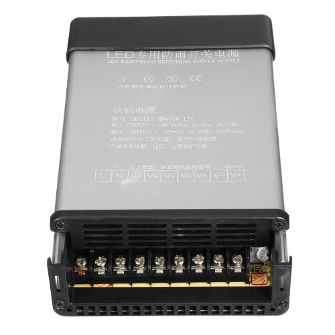
The Switching Power Supply 12V 400W with Luminous Characters 5V is a versatile and efficient power supply unit designed for a wide range of applications. It provides a stable 12V DC output with a maximum power rating of 400W, making it suitable for powering high-demand devices such as LED strips, industrial equipment, and motor drivers. Additionally, it features a 5V auxiliary output for powering low-power devices like microcontrollers or luminous character displays.
This power supply is commonly used in industrial automation, LED lighting systems, CNC machines, and DIY electronics projects. Its compact design, high efficiency, and built-in safety features make it a reliable choice for both professional and hobbyist applications.
Explore Projects Built with Switching Power Supply 12V 400W Luminous Characters 5V


Explore Projects Built with Switching Power Supply 12V 400W Luminous Characters 5V
Technical Specifications
Key Specifications
| Parameter | Value |
|---|---|
| Input Voltage Range | 110V AC or 220V AC (switchable) |
| Output Voltage (Main) | 12V DC |
| Output Voltage (Auxiliary) | 5V DC |
| Maximum Power Output | 400W |
| Maximum Current (12V) | 33.3A |
| Maximum Current (5V) | 2A |
| Efficiency | ≥85% |
| Operating Temperature | -10°C to +60°C |
| Cooling Method | Built-in fan |
| Dimensions | 215mm x 115mm x 50mm |
| Weight | ~1.2kg |
Pin Configuration and Descriptions
Input Terminals
| Pin Name | Description |
|---|---|
| L | Live AC input (110V/220V) |
| N | Neutral AC input |
| GND | Earth/ground connection |
Output Terminals
| Pin Name | Description |
|---|---|
| +V | Positive 12V DC output |
| -V | Negative 12V DC output (ground) |
| +5V | Positive 5V DC auxiliary output |
| GND | Ground for 5V auxiliary output |
Adjustment
| Pin Name | Description |
|---|---|
| V-ADJ | Voltage adjustment for 12V output (±10%) |
Usage Instructions
How to Use the Component in a Circuit
Input Connection:
- Ensure the input voltage selector switch is set to the correct position (110V or 220V) based on your local AC mains supply.
- Connect the live (L), neutral (N), and ground (GND) wires to the corresponding input terminals.
Output Connection:
- Connect the device or load to the +V and -V terminals for 12V DC output.
- If using the 5V auxiliary output, connect the load to the +5V and GND terminals.
Voltage Adjustment:
- Use the V-ADJ potentiometer to fine-tune the 12V output voltage within a ±10% range if required.
Cooling:
- Ensure proper ventilation around the power supply to allow the built-in fan to operate effectively.
Safety:
- Avoid overloading the power supply beyond its rated capacity (400W for 12V and 10W for 5V).
- Use appropriate fuses or circuit breakers for added protection.
Important Considerations and Best Practices
- Always double-check the input voltage selector switch before powering on the unit.
- Use appropriately rated wires for both input and output connections to handle the current safely.
- Avoid exposing the power supply to moisture or extreme temperatures.
- If using the 5V auxiliary output for microcontrollers like Arduino, ensure the current draw does not exceed 2A.
Example: Connecting to an Arduino UNO
The 5V auxiliary output can be used to power an Arduino UNO. Below is an example code to control an LED strip powered by the 12V output.
// Example code to control an LED strip using Arduino UNO
// Ensure the LED strip is connected to the 12V output of the power supply
// and the Arduino is powered by the 5V auxiliary output.

const int ledPin = 9; // PWM pin connected to the LED strip

void setup() {
  pinMode(ledPin, OUTPUT); // Set the LED pin as an output
}

void loop() {
  // Gradually increase brightness
  for (int brightness = 0; brightness <= 255; brightness++) {
    analogWrite(ledPin, brightness); // Set PWM duty cycle
    delay(10); // Small delay for smooth transition
  }

  // Gradually decrease brightness
  for (int brightness = 255; brightness >= 0; brightness--) {
    analogWrite(ledPin, brightness); // Set PWM duty cycle
    delay(10); // Small delay for smooth transition
  }
}
Troubleshooting and FAQs
Common Issues and Solutions
No Output Voltage:
- Ensure the input voltage selector switch is set correctly (110V or 220V).
- Check the AC input connections for loose or incorrect wiring.
- Verify that the power supply is not overloaded.
Overheating:
- Ensure proper ventilation and that the built-in fan is operational.
- Reduce the load if the power supply is running near its maximum capacity.
Voltage Fluctuations:
- Use the V-ADJ potentiometer to stabilize the output voltage.
- Check for loose connections on the output terminals.
5V Auxiliary Output Not Working:
- Ensure the current draw on the 5V output does not exceed 2A.
- Verify the connections to the +5V and GND terminals.
FAQs
Q: Can I use this power supply for both 12V and 5V devices simultaneously?
A: Yes, the power supply is designed to provide both 12V and 5V outputs simultaneously. Ensure the total power consumption does not exceed the rated capacity.
Q: Is the power supply suitable for outdoor use?
A: No, this power supply is not waterproof or weatherproof. It should only be used in dry, indoor environments.
Q: Can I adjust the 5V auxiliary output voltage?
A: No, the 5V auxiliary output is fixed and cannot be adjusted. Only the 12V output can be fine-tuned using the V-ADJ potentiometer.
Q: What happens if I overload the power supply?
A: The power supply has built-in protection features, such as overcurrent and overvoltage protection, which will shut it down to prevent damage. Reduce the load and restart the power supply.