How to Use rf transmitter: Examples, Pinouts, and Specs
Introduction
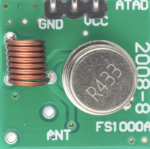
An RF transmitter is a device that generates and transmits radio frequency (RF) signals for wireless communication. It is commonly used in applications such as remote controls, wireless sensors, IoT devices, and other systems requiring data transmission over the air. The RF transmitter works by modulating a carrier signal with the data to be transmitted and sending it through an antenna.
Explore Projects Built with rf transmitter


Explore Projects Built with rf transmitter
Common Applications and Use Cases
- Remote control systems (e.g., garage doors, drones, and toys)
- Wireless sensor networks
- Internet of Things (IoT) devices
- Home automation systems
- Short-range communication systems
Technical Specifications
Below are the general technical specifications for a typical RF transmitter module (e.g., 433 MHz RF transmitter):
| Parameter | Value |
|---|---|
| Operating Frequency | 315 MHz / 433 MHz (common models) |
| Operating Voltage | 3.3V - 12V |
| Operating Current | 10 mA - 40 mA |
| Transmission Range | Up to 100 meters (line of sight) |
| Modulation Type | Amplitude Shift Keying (ASK) |
| Data Rate | Up to 10 kbps |
| Antenna | External (wire or PCB antenna) |
Pin Configuration and Descriptions
The RF transmitter module typically has 4 pins. Below is the pinout description:
| Pin | Name | Description |
|---|---|---|
| 1 | VCC | Power supply pin. Connect to a voltage source (3.3V to 12V, depending on model). |
| 2 | DATA | Data input pin. Connect to the microcontroller or data source. |
| 3 | GND | Ground pin. Connect to the ground of the circuit. |
| 4 | ANT | Antenna pin. Connect to an external antenna for better signal transmission. |
Usage Instructions
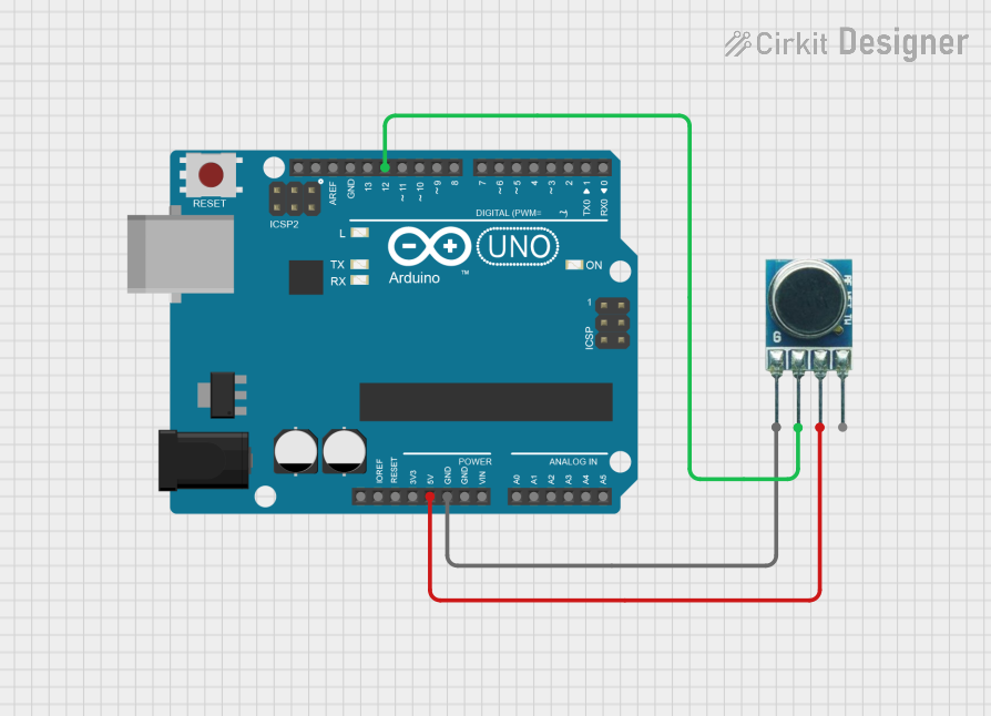
How to Use the RF Transmitter in a Circuit
- Power the Module: Connect the VCC pin to a power source (e.g., 5V from an Arduino UNO) and the GND pin to the ground.
- Connect the Data Pin: Attach the DATA pin to the microcontroller's digital output pin or a data source.
- Attach an Antenna: Connect a wire or PCB antenna to the ANT pin to improve the transmission range.
- Send Data: Use the microcontroller to send digital signals (e.g., HIGH/LOW) to the DATA pin. The RF transmitter will modulate and transmit the signal.
Important Considerations and Best Practices
- Antenna Design: Use a properly sized antenna (e.g., 17 cm for 433 MHz) to maximize range and signal quality.
- Power Supply: Ensure a stable power supply to avoid signal distortion.
- Interference: Minimize interference by keeping the transmitter away from other RF devices operating on the same frequency.
- Line of Sight: For maximum range, ensure there are no obstacles between the transmitter and receiver.
Example: Using the RF Transmitter with Arduino UNO
Below is an example of how to use the RF transmitter with an Arduino UNO to send data:
// Example: Sending data using an RF transmitter with Arduino UNO
// Library: No external library is required for basic transmission

int dataPin = 12; // Connect the DATA pin of the RF transmitter to pin 12

void setup() {
  pinMode(dataPin, OUTPUT); // Set the data pin as an output
}

void loop() {
  digitalWrite(dataPin, HIGH); // Send a HIGH signal
  delay(1000);                 // Wait for 1 second
  digitalWrite(dataPin, LOW);  // Send a LOW signal
  delay(1000);                 // Wait for 1 second
}
Troubleshooting and FAQs
Common Issues and Solutions
No Signal Transmission
- Cause: Incorrect wiring or loose connections.
- Solution: Double-check all connections, especially the VCC, GND, and DATA pins.
Short Transmission Range
- Cause: Poor antenna design or placement.
- Solution: Use a properly sized antenna and ensure it is positioned away from obstructions.
Interference with Other Devices
- Cause: Multiple devices operating on the same frequency.
- Solution: Use a different frequency module (e.g., 315 MHz instead of 433 MHz) or reduce interference sources.
Unstable Signal
- Cause: Insufficient power supply or noisy environment.
- Solution: Use a stable power source and add decoupling capacitors near the VCC pin.
FAQs
Q: Can I use the RF transmitter without an antenna?
A: While it is possible, the transmission range and signal quality will be significantly reduced. Always use an antenna for optimal performance.
Q: What is the maximum range of an RF transmitter?
A: The range depends on the module, antenna, and environment. Typically, it can reach up to 100 meters in line-of-sight conditions.
Q: Can I use multiple RF transmitters in the same area?
A: Yes, but ensure they operate on different frequencies or use unique data encoding to avoid interference.
Q: Is the RF transmitter compatible with all microcontrollers?
A: Yes, as long as the microcontroller can output digital signals within the module's operating voltage range.