How to Use SparkFun RedBoard: Examples, Pinouts, and Specs
Introduction
The SparkFun RedBoard is an Arduino-compatible development board that serves as an excellent platform for hobbyists, educators, and professionals to explore the world of electronics. It is designed to be as easy to use as possible, making it ideal for educational purposes and for those new to electronics and programming. The RedBoard can be used for a wide range of applications, from simple LED light shows to complex robotics projects.
Explore Projects Built with SparkFun RedBoard
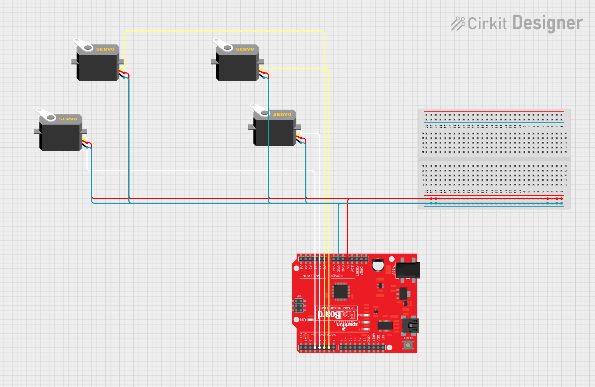
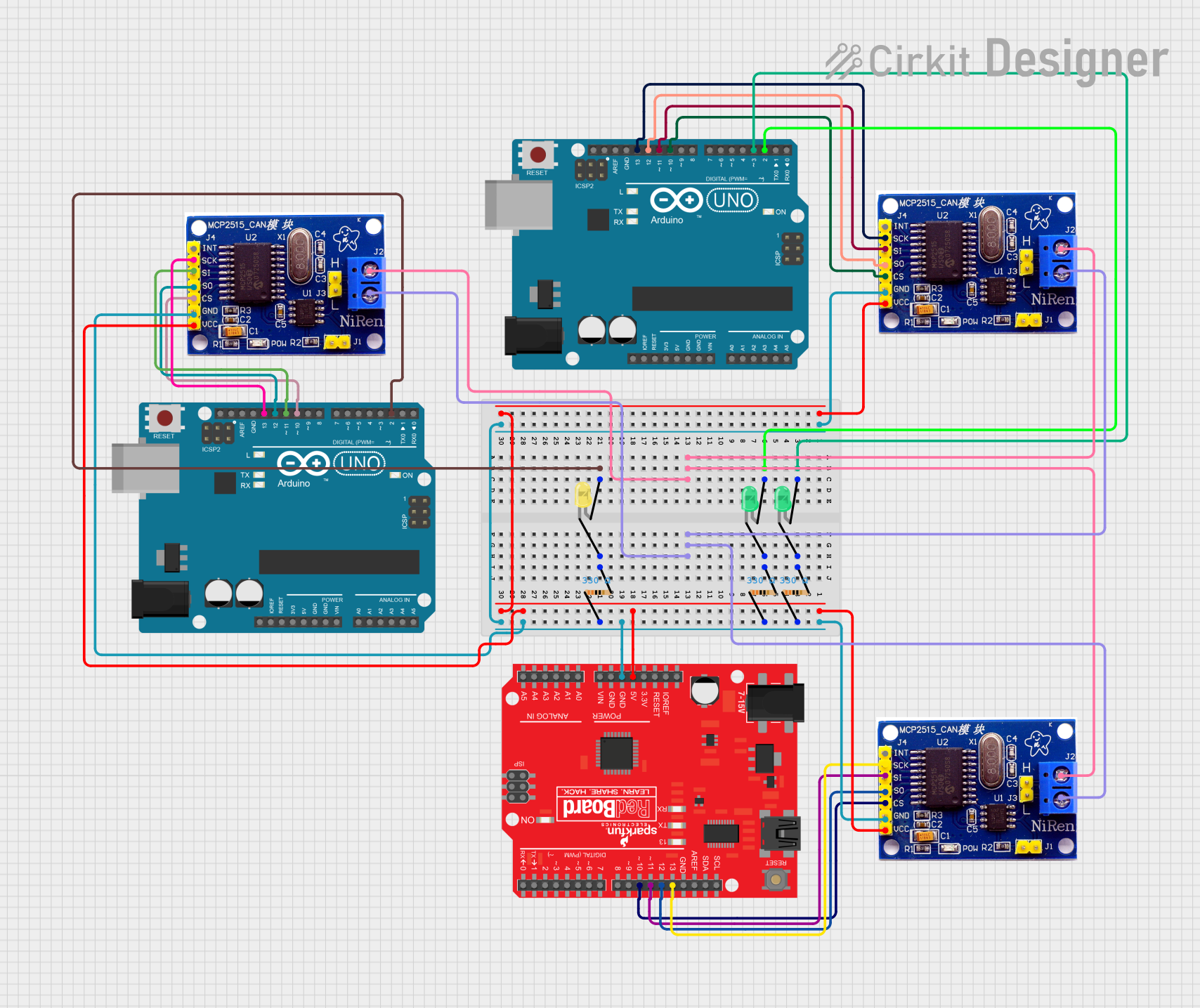
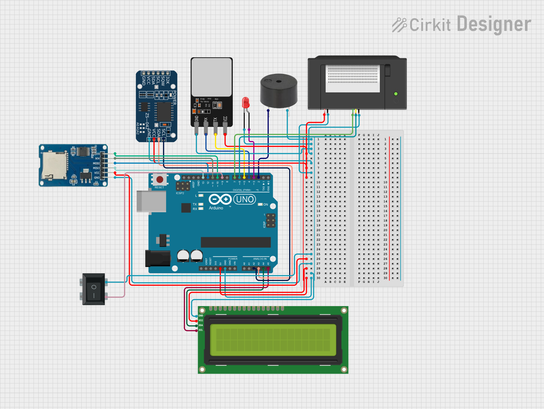

Explore Projects Built with SparkFun RedBoard
Technical Specifications
General Specifications
- Microcontroller: ATmega328
- Operating Voltage: 5V
- Input Voltage (recommended): 7-15V
- Input Voltage (limits): 6-20V
- Digital I/O Pins: 14 (of which 6 provide PWM output)
- Analog Input Pins: 6
- DC Current per I/O Pin: 40 mA
- DC Current for 3.3V Pin: 50 mA
- Flash Memory: 32 KB (ATmega328) of which 0.5 KB used by bootloader
- SRAM: 2 KB (ATmega328)
- EEPROM: 1 KB (ATmega328)
- Clock Speed: 16 MHz
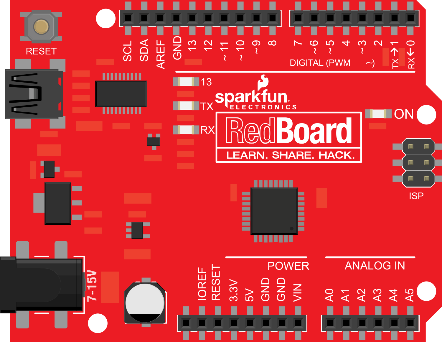
Pin Configuration
| Pin Number | Function | Description |
|---|---|---|
| 1 | RESET | Resets the microcontroller |
| 2-13 | Digital I/O | Digital input/output pins |
| A0-A5 | Analog Input | Analog input pins |
| 3, 5, 6, 9, 10, 11 | PWM Output | Pins capable of providing PWM output |
| AREF | Analog Reference | Reference voltage for the analog inputs |
| GND | Ground | Ground pin |
| RST | Reset | Reset pin, active low |
| 5V | 5V Power | Regulated power supply for the board and components |
| 3.3V | 3.3V Power | Regulated power supply for low voltage components |
| VIN | Voltage Input | Unregulated input voltage to the board |
Usage Instructions
Setting Up the RedBoard
- Connect to a Computer: Use a USB cable to connect the RedBoard to your computer.
- Install the Arduino IDE: Download and install the Arduino Integrated Development Environment (IDE) from the official Arduino website.
- Select the Board: In the Arduino IDE, go to
Tools > Boardand select "Arduino UNO" as the board type, since the RedBoard is compatible with UNO. - Select the Port: Go to
Tools > Portand select the port that corresponds to the RedBoard.
Writing a Basic Sketch
Here is a simple example of how to blink an LED connected to pin 13 of the RedBoard:
// The setup function runs once when you press reset or power the board
void setup() {
  // Initialize digital pin 13 as an output.
  pinMode(13, OUTPUT);
}

// The loop function runs over and over again forever
void loop() {
  digitalWrite(13, HIGH);   // Turn the LED on (HIGH is the voltage level)
  delay(1000);              // Wait for a second
  digitalWrite(13, LOW);    // Turn the LED off by making the voltage LOW
  delay(1000);              // Wait for a second
}
Important Considerations and Best Practices
- Power Supply: Ensure that the power supply does not exceed the recommended voltage limits to prevent damage to the board.
- I/O Pin Current: Do not draw more than 40 mA from a single I/O pin.
- Short Circuits: Avoid creating short circuits, which can damage the board and connected components.
- Static Discharge: Handle the board with care to prevent damage from static discharge.
Troubleshooting and FAQs
Common Issues
- Board Not Recognized: Ensure that the USB drivers are installed correctly and that the cable is functioning.
- Sketch Not Uploading: Check the selected board and port in the Arduino IDE. Ensure that the correct board ("Arduino UNO") and the port corresponding to the RedBoard are selected.
- LED Not Blinking: Verify that the LED is connected correctly with the anode to pin 13 and the cathode to GND. Also, check the LED with a multimeter to ensure it is not defective.
FAQs
Q: Can I use the RedBoard with Arduino shields? A: Yes, the RedBoard is compatible with most Arduino UNO shields.
Q: What is the difference between the RedBoard and the Arduino UNO? A: The RedBoard is functionally similar to the Arduino UNO but may have differences in layout and USB-to-serial chips.
Q: How do I reset the RedBoard? A: You can reset the RedBoard by pressing the onboard reset button or by connecting the RESET pin to GND briefly.
For further assistance, consult the SparkFun RedBoard forums and the extensive online community resources.