Cirkit Designer Logo
Cirkit Designer
Your all-in-one circuit design IDE
Home / 
Component Documentation

How to Use GUVA-S12SD: Examples, Pinouts, and Specs

Image of GUVA-S12SD
Cirkit Designer LogoDesign with GUVA-S12SD in Cirkit Designer

Introduction

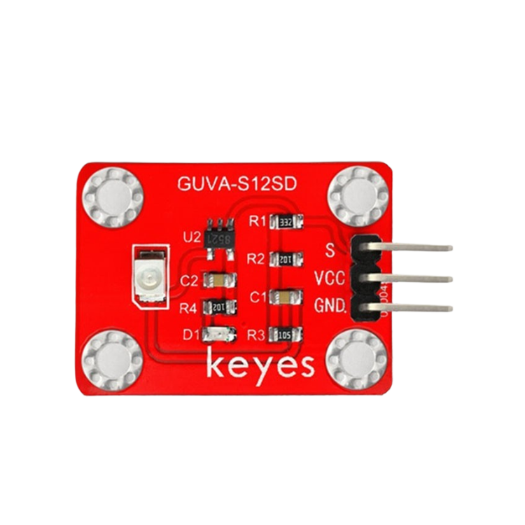
The GUVA-S12SD is a UV light sensor manufactured by KEYES, with the part ID "UNO". This sensor is designed to detect ultraviolet (UV) radiation in the wavelength range of 240 to 370 nm. It outputs an analog voltage proportional to the intensity of UV light, making it an ideal choice for applications requiring UV monitoring.

Explore Projects Built with GUVA-S12SD

Use Cirkit Designer to design, explore, and prototype these projects online. Some projects support real-time simulation. Click "Open Project" to start designing instantly!
Cellular-Enabled IoT Device with Real-Time Clock and Power Management
Image of LRCM PHASE 2 BASIC: A project utilizing GUVA-S12SD in a practical application
This circuit features a LilyGo-SIM7000G module for cellular communication and GPS functionality, interfaced with an RTC DS3231 for real-time clock capabilities. It includes voltage sensing through two voltage sensor modules, and uses an 8-channel opto-coupler for isolating different parts of the circuit. Power management is handled by a buck converter connected to a DC power source and batteries, with a fuse for protection and a rocker switch for on/off control. Additionally, there's an LED for indication purposes.
Cirkit Designer LogoOpen Project in Cirkit Designer
ESP32-S3 Battery-Powered Environmental Monitoring System with OLED Display
Image of Diagram wiring: A project utilizing GUVA-S12SD in a practical application
This circuit is a sensor and display system powered by a UPS module with a 12V power supply and 18650 batteries. It includes an ESP32 microcontroller that interfaces with various sensors (DHT22, Strain Gauge, MPU-6050, ADXL345) and an OLED display, with power regulation provided by a step-down buck converter.
Cirkit Designer LogoOpen Project in Cirkit Designer
ESP32-S3 Based Vibration Detection System with TFT Display and Power Backup
Image of IOT Thesis: A project utilizing GUVA-S12SD in a practical application
This circuit features an ESP32-S3 microcontroller connected to various peripherals including an ADXL355 accelerometer, an SW-420 vibration sensor, a buzzer module, and an ILI9341 TFT display. The ESP32-S3 manages sensor inputs and provides output to the display and buzzer. Power management is handled by a 12V to 5V step-down converter, and a UPS ensures uninterrupted power supply, with a rocker switch to control the power flow.
Cirkit Designer LogoOpen Project in Cirkit Designer
Solar-Powered Environmental Monitoring System with ESP32-C3 and MPPT Charge Control
Image of Gen Shed Xiao ESP32C3 INA3221 AHT21 -1: A project utilizing GUVA-S12SD in a practical application
This circuit is designed for solar energy management and monitoring. It includes a 12V AGM battery charged by solar panels through an MPPT charge controller, with voltage monitoring provided by an INA3221 sensor. Additionally, a 3.7V battery is connected to an ESP32-C3 microcontroller and an AHT21 sensor for environmental data collection, with power management handled by a Waveshare Solar Manager.
Cirkit Designer LogoOpen Project in Cirkit Designer

Explore Projects Built with GUVA-S12SD

Use Cirkit Designer to design, explore, and prototype these projects online. Some projects support real-time simulation. Click "Open Project" to start designing instantly!
Image of LRCM PHASE 2 BASIC: A project utilizing GUVA-S12SD in a practical application
Cellular-Enabled IoT Device with Real-Time Clock and Power Management
This circuit features a LilyGo-SIM7000G module for cellular communication and GPS functionality, interfaced with an RTC DS3231 for real-time clock capabilities. It includes voltage sensing through two voltage sensor modules, and uses an 8-channel opto-coupler for isolating different parts of the circuit. Power management is handled by a buck converter connected to a DC power source and batteries, with a fuse for protection and a rocker switch for on/off control. Additionally, there's an LED for indication purposes.
Cirkit Designer LogoOpen Project in Cirkit Designer
Image of Diagram wiring: A project utilizing GUVA-S12SD in a practical application
ESP32-S3 Battery-Powered Environmental Monitoring System with OLED Display
This circuit is a sensor and display system powered by a UPS module with a 12V power supply and 18650 batteries. It includes an ESP32 microcontroller that interfaces with various sensors (DHT22, Strain Gauge, MPU-6050, ADXL345) and an OLED display, with power regulation provided by a step-down buck converter.
Cirkit Designer LogoOpen Project in Cirkit Designer
Image of IOT Thesis: A project utilizing GUVA-S12SD in a practical application
ESP32-S3 Based Vibration Detection System with TFT Display and Power Backup
This circuit features an ESP32-S3 microcontroller connected to various peripherals including an ADXL355 accelerometer, an SW-420 vibration sensor, a buzzer module, and an ILI9341 TFT display. The ESP32-S3 manages sensor inputs and provides output to the display and buzzer. Power management is handled by a 12V to 5V step-down converter, and a UPS ensures uninterrupted power supply, with a rocker switch to control the power flow.
Cirkit Designer LogoOpen Project in Cirkit Designer
Image of Gen Shed Xiao ESP32C3 INA3221 AHT21 -1: A project utilizing GUVA-S12SD in a practical application
Solar-Powered Environmental Monitoring System with ESP32-C3 and MPPT Charge Control
This circuit is designed for solar energy management and monitoring. It includes a 12V AGM battery charged by solar panels through an MPPT charge controller, with voltage monitoring provided by an INA3221 sensor. Additionally, a 3.7V battery is connected to an ESP32-C3 microcontroller and an AHT21 sensor for environmental data collection, with power management handled by a Waveshare Solar Manager.
Cirkit Designer LogoOpen Project in Cirkit Designer

Common Applications:

  • UV index measurement for environmental monitoring
  • Sun exposure tracking for health and safety
  • UV light detection in sterilization systems
  • Monitoring UV levels in industrial and agricultural settings

Technical Specifications

The GUVA-S12SD UV sensor is a compact and efficient device with the following key specifications:

Parameter Value
Operating Voltage 3.3V to 5V
Operating Current 0.06 mA (typical)
Wavelength Range 240 nm to 370 nm
Output Voltage Range 0V to Vcc (proportional to UV intensity)
Operating Temperature -30°C to +85°C
Dimensions 20 mm x 10 mm x 2 mm

Pin Configuration

The GUVA-S12SD sensor has three pins, as described in the table below:

Pin Name Description
1 VCC Power supply input (3.3V to 5V)
2 GND Ground connection
3 OUT Analog output voltage proportional to UV intensity

Usage Instructions

Connecting the GUVA-S12SD to a Circuit

  1. Power Supply: Connect the VCC pin to a 3.3V or 5V power source, depending on your system's voltage level.
  2. Ground: Connect the GND pin to the ground of your circuit.
  3. Output: Connect the OUT pin to an analog input pin of your microcontroller or ADC (Analog-to-Digital Converter) to read the UV intensity.

Important Considerations:

  • Ensure the sensor is not exposed to excessive heat or humidity, as this may affect its performance.
  • Avoid placing the sensor in direct contact with water or other liquids.
  • Use a stable power supply to minimize noise in the analog output signal.
  • The sensor's output voltage is proportional to UV intensity, so calibration may be required for precise measurements.

Example: Using GUVA-S12SD with Arduino UNO

The following example demonstrates how to connect and read data from the GUVA-S12SD sensor using an Arduino UNO:

Circuit Diagram:

  • Connect the VCC pin of the sensor to the 5V pin on the Arduino.
  • Connect the GND pin of the sensor to the GND pin on the Arduino.
  • Connect the OUT pin of the sensor to the A0 analog input pin on the Arduino.

Arduino Code:

// GUVA-S12SD UV Sensor Example with Arduino UNO
// Reads the analog output from the sensor and calculates UV intensity.

const int uvSensorPin = A0; // Analog pin connected to the sensor's OUT pin
float uvVoltage = 0.0;      // Variable to store the sensor's output voltage
float uvIntensity = 0.0;    // Variable to store the calculated UV intensity

void setup() {
  Serial.begin(9600); // Initialize serial communication at 9600 baud
  pinMode(uvSensorPin, INPUT); // Set the sensor pin as input
}

void loop() {
  int sensorValue = analogRead(uvSensorPin); // Read the analog value
  uvVoltage = sensorValue * (5.0 / 1023.0); // Convert to voltage (5V reference)
  
  // Convert voltage to UV intensity (example conversion factor: 307)
  // Note: The conversion factor depends on the sensor's calibration.
  uvIntensity = uvVoltage * 307.0; 
  
  // Print the results to the Serial Monitor
  Serial.print("UV Voltage: ");
  Serial.print(uvVoltage);
  Serial.print(" V, UV Intensity: ");
  Serial.print(uvIntensity);
  Serial.println(" mW/m^2");
  
  delay(1000); // Wait for 1 second before the next reading
}

Notes:

  • The conversion factor (307 in the example) is an approximate value. For accurate results, calibrate the sensor using a known UV light source.
  • The output voltage is directly proportional to UV intensity, so higher UV levels will result in higher output voltages.

Troubleshooting and FAQs

Common Issues and Solutions:

  1. No Output Voltage:

    • Ensure the sensor is properly connected to the power supply and ground.
    • Verify that the input voltage is within the specified range (3.3V to 5V).
  2. Inconsistent Readings:

    • Check for electrical noise or unstable power supply.
    • Ensure the sensor is not exposed to sudden changes in temperature or humidity.
  3. Low Sensitivity:

    • Verify that the UV light source is within the sensor's wavelength range (240-370 nm).
    • Clean the sensor surface to remove any dust or debris that may block UV light.

FAQs:

Q: Can the GUVA-S12SD detect visible light?
A: No, the GUVA-S12SD is specifically designed to detect UV light in the 240-370 nm range. It is not sensitive to visible light.

Q: How do I calibrate the sensor?
A: To calibrate the sensor, expose it to a known UV light source with a specific intensity. Measure the output voltage and calculate the conversion factor to relate voltage to UV intensity.

Q: Can I use the sensor outdoors?
A: Yes, the sensor can be used outdoors, but it should be protected from water and extreme environmental conditions to ensure reliable operation.

Q: What is the maximum UV intensity the sensor can measure?
A: The maximum measurable UV intensity depends on the sensor's output voltage range and the calibration factor. Typically, the sensor can measure UV intensities up to several hundred mW/m².