Cirkit Designer
Your all-in-one circuit design IDE
Home /
Component Documentation
How to Use Floating Switch: Examples, Pinouts, and Specs
Introduction
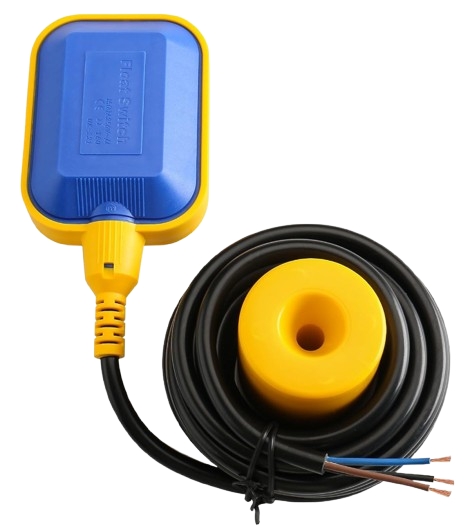
A floating switch is a device used to detect the level of liquid within a tank. It floats on the surface of the liquid and activates a switch when the liquid reaches a certain level. This component is commonly used in applications such as sump pumps, water tanks, and other liquid level control systems. The floating switch is a reliable and cost-effective solution for automating the control of liquid levels in various industrial and domestic settings.
Explore Projects Built with Floating Switch
Arduino-Based Automatic Drainage Water Monitoring & Flood Control System with Air Quality and Pressure Sensors
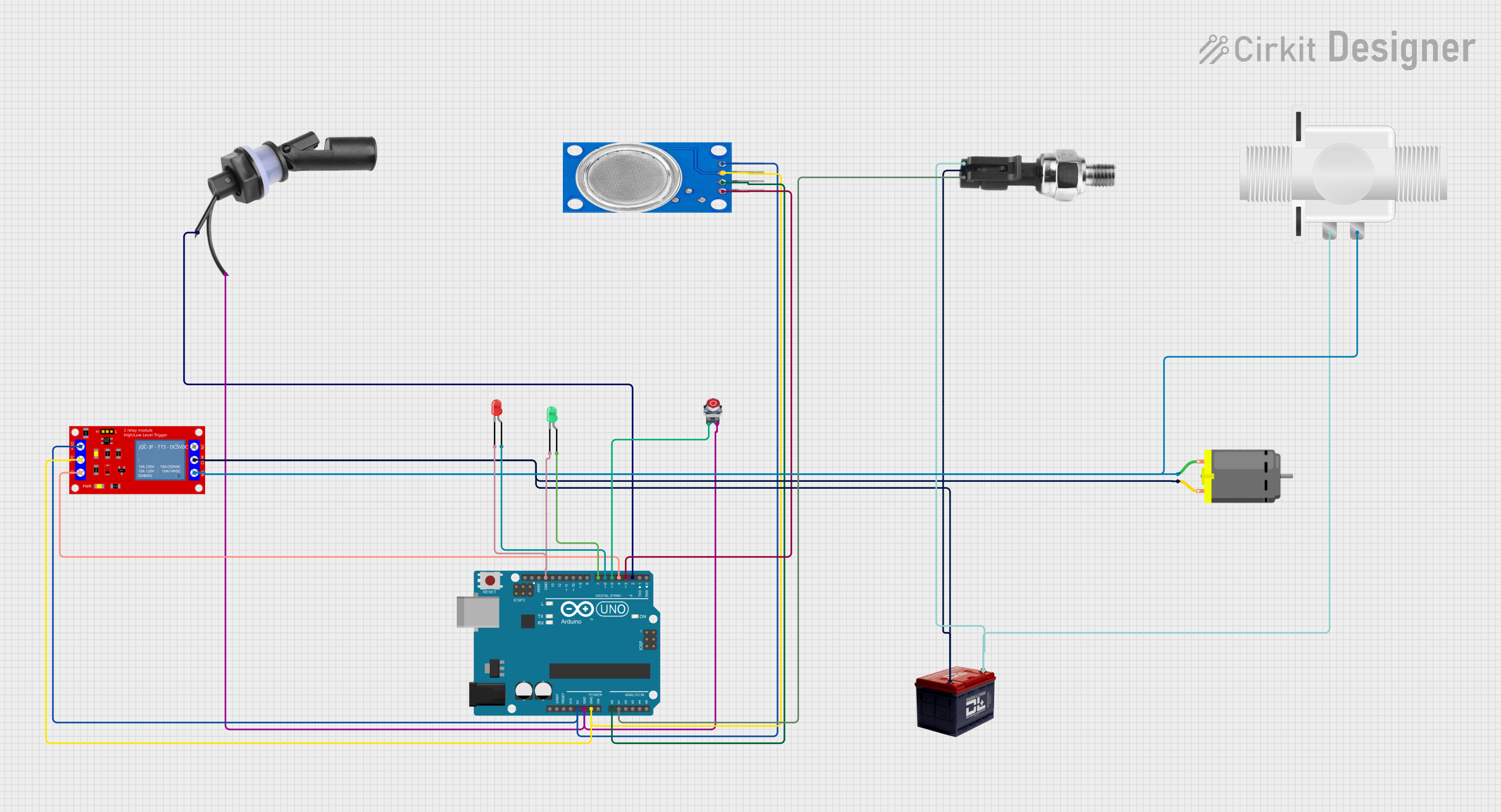
This circuit is an Arduino-based automatic drainage water monitoring and flood control system. It uses a float switch, MQ135 air quality sensor, and pressure sensor to monitor environmental conditions and control a relay module that operates a DC motor and solenoid valve. The system includes LEDs for status indication and a stop button to manually halt operations.
Toggle Switch Controlled Lamp Circuit with Banana Sockets

This circuit consists of two toggle switches and a red lamp connected to panel mount banana sockets. The switches control the connection between the red and black banana sockets, allowing the lamp to be turned on or off depending on the switch positions.
Digital Logic State Indicator with Flip-Flops and Logic Gates

This circuit is a digital logic system that uses a DIP switch to provide input to a network of flip-flops and logic gates, which process the input signals. The output of this processing is likely indicated by LEDs, which are connected through resistors to limit current. The circuit functions autonomously without a microcontroller, relying on the inherent properties of the digital components to perform its logic operations.
Arduino-Based Battery-Powered Water Level Monitoring System with Siren Alert
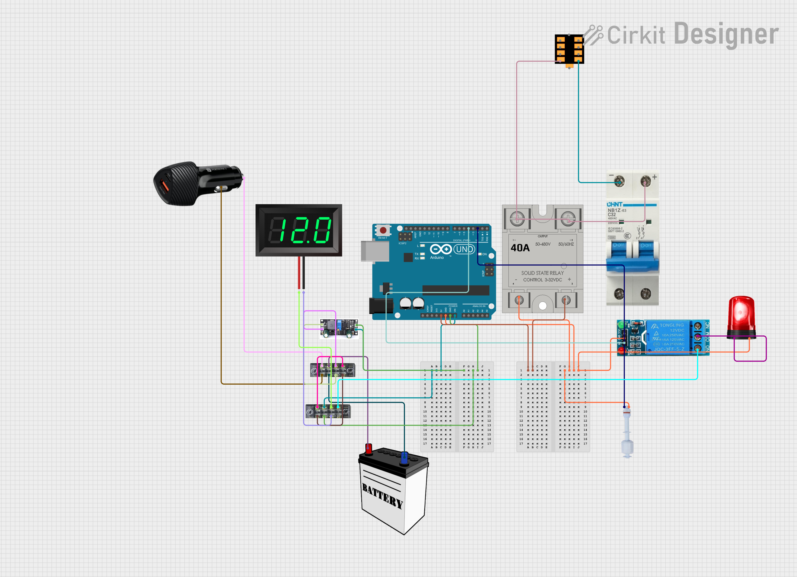
This circuit is a water level monitoring and alert system powered by a 12V battery and managed by an Arduino UNO. It uses a float switch to detect water levels, a relay to control a siren for alerts, and a solid-state relay for additional control. The system includes a charge controller for battery management and a voltmeter for monitoring the battery voltage.
Explore Projects Built with Floating Switch
Arduino-Based Automatic Drainage Water Monitoring & Flood Control System with Air Quality and Pressure Sensors
This circuit is an Arduino-based automatic drainage water monitoring and flood control system. It uses a float switch, MQ135 air quality sensor, and pressure sensor to monitor environmental conditions and control a relay module that operates a DC motor and solenoid valve. The system includes LEDs for status indication and a stop button to manually halt operations.
Toggle Switch Controlled Lamp Circuit with Banana Sockets
This circuit consists of two toggle switches and a red lamp connected to panel mount banana sockets. The switches control the connection between the red and black banana sockets, allowing the lamp to be turned on or off depending on the switch positions.
Digital Logic State Indicator with Flip-Flops and Logic Gates
This circuit is a digital logic system that uses a DIP switch to provide input to a network of flip-flops and logic gates, which process the input signals. The output of this processing is likely indicated by LEDs, which are connected through resistors to limit current. The circuit functions autonomously without a microcontroller, relying on the inherent properties of the digital components to perform its logic operations.
Arduino-Based Battery-Powered Water Level Monitoring System with Siren Alert
This circuit is a water level monitoring and alert system powered by a 12V battery and managed by an Arduino UNO. It uses a float switch to detect water levels, a relay to control a siren for alerts, and a solid-state relay for additional control. The system includes a charge controller for battery management and a voltmeter for monitoring the battery voltage.
Technical Specifications
Key Technical Details
| Parameter | Value |
|---|---|
| Operating Voltage | 5V to 220V AC/DC |
| Max Current | 0.5A to 1.5A |
| Contact Resistance | ≤ 100 mΩ |
| Insulation | ≥ 100 MΩ |
| Operating Temp | -10°C to 60°C |
| Material | Polypropylene (PP) or Nylon |
| Cable Length | 1m to 5m |
Pin Configuration and Descriptions
| Pin Number | Description |
|---|---|
| 1 | Common (COM) |
| 2 | Normally Open (NO) |
| 3 | Normally Closed (NC) |
Usage Instructions
How to Use the Component in a Circuit
- Identify the Pins: Determine the Common (COM), Normally Open (NO), and Normally Closed (NC) pins on the floating switch.
- Connect to Power Source: Connect the COM pin to the power source (e.g., 5V from an Arduino).
- Connect to Load: Connect the NO or NC pin to the load (e.g., a pump or an indicator light). Use the NO pin if you want the load to be activated when the liquid reaches the set level. Use the NC pin if you want the load to be deactivated when the liquid reaches the set level.
- Secure the Switch: Place the floating switch in the tank, ensuring it can move freely with the liquid level.
Important Considerations and Best Practices
- Orientation: Ensure the floating switch is installed in the correct orientation to function properly.
- Cable Management: Secure the cable to prevent tangling or damage.
- Environmental Conditions: Verify that the switch material is compatible with the liquid and environmental conditions.
- Testing: Test the switch operation before finalizing the installation.
Example Circuit with Arduino UNO
// Example code to read the state of a floating switch with Arduino UNO

const int floatSwitchPin = 2; // Pin connected to the floating switch
const int ledPin = 13;        // Pin connected to an LED for indication

void setup() {
  pinMode(floatSwitchPin, INPUT); // Set the float switch pin as input
  pinMode(ledPin, OUTPUT);        // Set the LED pin as output
  Serial.begin(9600);             // Initialize serial communication
}

void loop() {
  int switchState = digitalRead(floatSwitchPin); // Read the state of the switch

  if (switchState == HIGH) {
    digitalWrite(ledPin, HIGH); // Turn on the LED if the switch is HIGH
    Serial.println("Liquid level is high!");
  } else {
    digitalWrite(ledPin, LOW);  // Turn off the LED if the switch is LOW
    Serial.println("Liquid level is low.");
  }

  delay(500); // Wait for 500 milliseconds before the next reading
}
Troubleshooting and FAQs
Common Issues Users Might Face
- Switch Not Activating: Ensure the switch is properly oriented and the liquid level is sufficient to activate the switch.
- Intermittent Operation: Check for loose connections or damaged cables.
- Incorrect Readings: Verify the pin connections and ensure the switch is not obstructed.
Solutions and Tips for Troubleshooting
- Check Connections: Ensure all connections are secure and correct.
- Test the Switch: Manually move the float to test the switch operation.
- Inspect the Cable: Look for any signs of wear or damage to the cable.
- Verify Compatibility: Ensure the switch material is suitable for the liquid and environmental conditions.
By following this documentation, users can effectively utilize the floating switch in their liquid level control applications, ensuring reliable and efficient operation.