How to Use SCC: Examples, Pinouts, and Specs
Introduction
A Switching Converter Controller (SCC) is a device designed to regulate the output voltage of a switching power supply. It achieves this by controlling the duty cycle of the switching elements, ensuring efficient power conversion and stable output. SCCs are widely used in power management systems due to their ability to handle high efficiency and flexibility in various applications.
Explore Projects Built with SCC
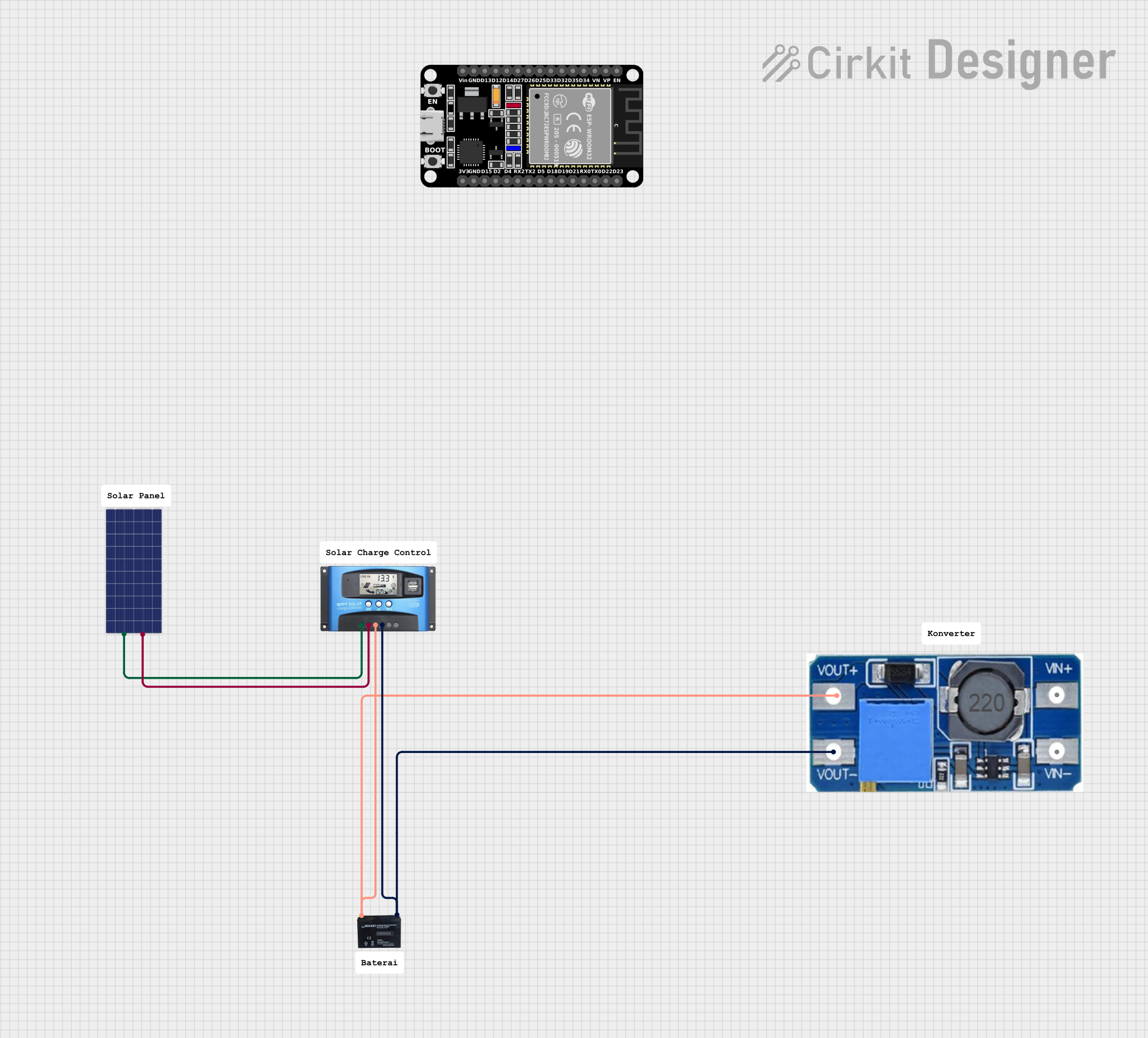
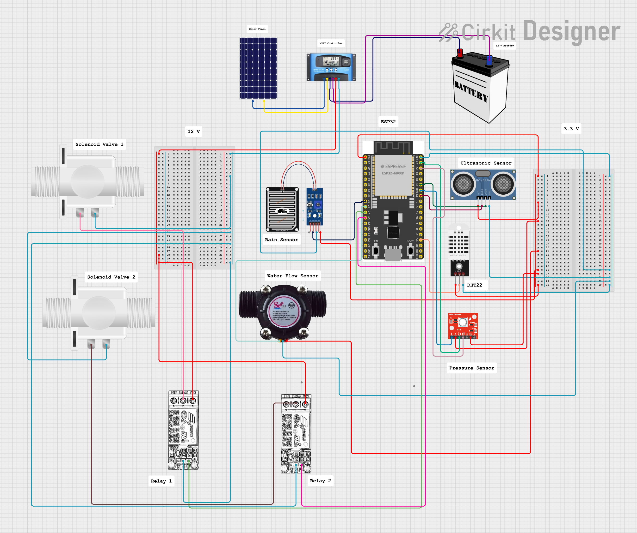
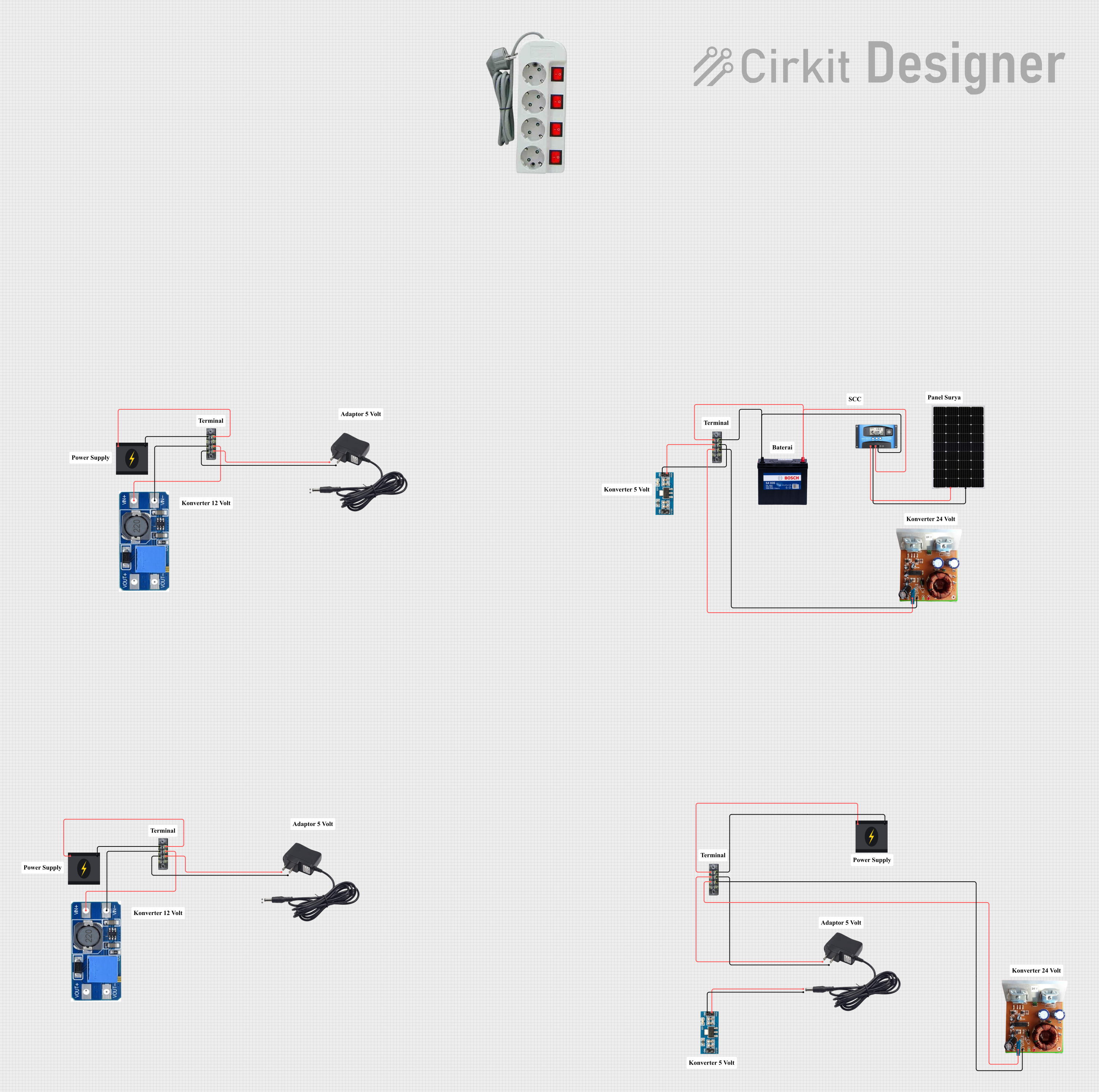

Explore Projects Built with SCC
Common Applications and Use Cases
- DC-DC converters (e.g., buck, boost, and buck-boost converters)
- Power supplies for microcontrollers and digital circuits
- Battery charging systems
- Renewable energy systems (e.g., solar inverters)
- LED drivers and lighting systems
Technical Specifications
Key Technical Details
| Parameter | Value/Range | Description |
|---|---|---|
| Input Voltage Range | 3.3V to 40V | Voltage range the SCC can accept |
| Output Voltage Range | 0.8V to 30V | Regulated output voltage range |
| Switching Frequency | 100 kHz to 1 MHz | Frequency of the switching elements |
| Efficiency | Up to 95% | Power conversion efficiency |
| Operating Temperature | -40°C to +125°C | Temperature range for reliable operation |
| Control Method | Pulse Width Modulation (PWM) | Method used to regulate the output |
| Package Type | SOIC-8, TSSOP-14, or QFN-16 | Common package types |
Pin Configuration and Descriptions
Example: SCC in a 14-Pin TSSOP Package
| Pin Number | Pin Name | Description |
|---|---|---|
| 1 | VIN | Input voltage pin; connects to the power source |
| 2 | VOUT | Regulated output voltage pin |
| 3 | FB | Feedback pin; monitors output voltage for regulation |
| 4 | COMP | Compensation pin; used for stability and loop control |
| 5 | EN | Enable pin; activates or deactivates the SCC |
| 6 | GND | Ground pin; connects to the system ground |
| 7 | SW | Switch pin; connects to the switching element (e.g., MOSFET) |
| 8 | RT/CLK | Timing resistor or clock input pin; sets the switching frequency |
| 9 | SS/TR | Soft-start or tracking pin; controls startup behavior |
| 10 | PG | Power good pin; indicates if the output voltage is within the desired range |
| 11 | SYNC | Synchronization pin; allows synchronization with an external clock |
| 12 | BOOT | Bootstrap pin; provides drive voltage for the high-side MOSFET |
| 13 | ILIM | Current limit pin; sets the maximum allowable current |
| 14 | NC | No connection; reserved for future use or left unconnected |
Usage Instructions
How to Use the SCC in a Circuit
- Power Supply Design: Select an appropriate input voltage source and ensure it falls within the SCC's input voltage range.
- Feedback Network: Design a voltage divider network for the feedback pin (FB) to set the desired output voltage.
- Switching Element: Connect a suitable MOSFET or other switching device to the SW pin.
- Inductor and Capacitor Selection: Choose an inductor and output capacitor based on the desired output voltage, current, and ripple requirements.
- Enable Pin: Use the EN pin to control the SCC's operation. Pull it high to enable the controller.
- Soft-Start: Configure the soft-start pin (SS/TR) to control the startup time and prevent inrush current.
- Synchronization: If needed, connect an external clock to the SYNC pin to synchronize the switching frequency.
Important Considerations and Best Practices
- Thermal Management: Ensure proper heat dissipation by using a heatsink or thermal vias if necessary.
- PCB Layout: Minimize the loop area of high-current paths to reduce electromagnetic interference (EMI).
- Stability: Use the COMP pin to fine-tune the compensation network for stable operation.
- Current Limiting: Set the ILIM pin to prevent overcurrent conditions and protect the circuit.
Example: Using SCC with an Arduino UNO
Below is an example of how to use an SCC to power an Arduino UNO with a regulated 5V output:
Circuit Connections
- Connect the SCC's VIN pin to a 12V DC power source.
- Set the feedback network to regulate the output voltage to 5V.
- Connect the SCC's VOUT pin to the Arduino UNO's 5V input pin.
- Use a 10 µH inductor and a 100 µF capacitor for the output filter.
Arduino Code Example
// Example code to monitor the SCC's power good (PG) pin
const int pgPin = 2; // Connect SCC's PG pin to Arduino digital pin 2
const int ledPin = 13; // Onboard LED pin

void setup() {
  pinMode(pgPin, INPUT); // Set PG pin as input
  pinMode(ledPin, OUTPUT); // Set LED pin as output
  digitalWrite(ledPin, LOW); // Turn off LED initially
  Serial.begin(9600); // Initialize serial communication
}

void loop() {
  int pgStatus = digitalRead(pgPin); // Read the PG pin status

  if (pgStatus == HIGH) {
    // If power is good, turn on the LED
    digitalWrite(ledPin, HIGH);
    Serial.println("Power Good: SCC output is stable.");
  } else {
    // If power is not good, turn off the LED
    digitalWrite(ledPin, LOW);
    Serial.println("Power Not Good: Check SCC output.");
  }

  delay(1000); // Wait for 1 second before checking again
}
Troubleshooting and FAQs
Common Issues and Solutions
| Issue | Possible Cause | Solution |
|---|---|---|
| Output voltage is unstable | Improper feedback network design | Verify and adjust the feedback resistors |
| SCC does not start | EN pin is not pulled high | Ensure the EN pin is connected to a high logic level |
| Excessive heat generation | Poor thermal management | Add heatsinks or improve PCB layout |
| High output ripple | Inadequate output capacitor | Use a capacitor with higher capacitance or lower ESR |
| Overcurrent protection triggers | Current limit set too low | Adjust the ILIM pin to a higher threshold |
FAQs
Can the SCC handle negative input voltages?
No, the SCC is designed for positive input voltages only. Ensure the input voltage is within the specified range.How do I synchronize multiple SCCs?
Use the SYNC pin to connect an external clock signal to synchronize the switching frequency of multiple SCCs.What happens if the feedback pin is left unconnected?
The SCC will not regulate the output voltage properly. Always connect the feedback pin to a voltage divider network.Can I use the SCC for AC-DC conversion?
No, the SCC is designed for DC-DC conversion. Use an appropriate rectifier circuit for AC-DC conversion before the SCC.
By following this documentation, users can effectively integrate the SCC into their power management systems and troubleshoot common issues.