
How to Use DS2Y-5-DC5V: Examples, Pinouts, and Specs
 Design with DS2Y-5-DC5V in Cirkit Designer
Introduction
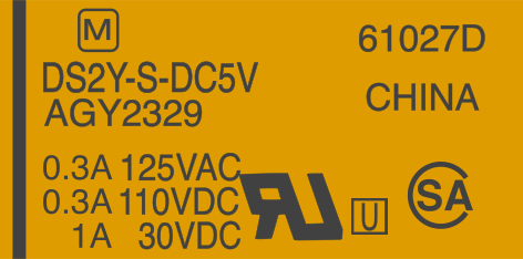
The DS2Y-5-DC5V is a miniature relay manufactured by Panasonic, designed for low voltage applications. This relay is commonly used in automation, control systems, and other electronic circuits requiring reliable switching. Its compact size and dependable performance make it ideal for space-constrained designs and applications where precision and durability are critical.
Explore Projects Built with DS2Y-5-DC5V
 Open Project in Cirkit Designer
 Open Project in Cirkit Designer
 Open Project in Cirkit Designer
 Open Project in Cirkit Designer
Explore Projects Built with DS2Y-5-DC5V
Open Project in Cirkit DesignerOpen Project in Cirkit DesignerOpen Project in Cirkit DesignerOpen Project in Cirkit DesignerCommon Applications
- Industrial automation systems
- Home appliances and HVAC systems
- Security and alarm systems
- Test and measurement equipment
- Low-power switching circuits
Technical Specifications
Key Technical Details
| Parameter | Value |
|---|---|
| Manufacturer | Panasonic |
| Part Number | DS2Y-5-DC5V |
| Coil Voltage | 5V DC |
| Coil Resistance | 178 Ω ±10% |
| Contact Configuration | DPDT (Double Pole Double Throw) |
| Contact Rating | 2A at 30V DC / 0.5A at 125V AC |
| Maximum Switching Voltage | 220V DC / 250V AC |
| Maximum Switching Current | 2A |
| Insulation Resistance | 1000 MΩ (at 500V DC) |
| Dielectric Strength | 1500V AC (1 minute) |
| Operating Time | Approx. 4 ms |
| Release Time | Approx. 4 ms |
| Dimensions | 20.2 x 10.2 x 9.8 mm |
| Weight | Approx. 4.5 g |
Pin Configuration and Descriptions
The DS2Y-5-DC5V relay has a total of 8 pins. The pinout is as follows:
| Pin Number | Description |
|---|---|
| 1 | Coil Terminal (Positive) |
| 2 | Coil Terminal (Negative) |
| 3 | Common Contact (Pole 1) |
| 4 | Normally Closed (NC) Contact 1 |
| 5 | Normally Open (NO) Contact 1 |
| 6 | Common Contact (Pole 2) |
| 7 | Normally Closed (NC) Contact 2 |
| 8 | Normally Open (NO) Contact 2 |
Usage Instructions
How to Use the DS2Y-5-DC5V in a Circuit
- Power the Coil: Connect the coil terminals (pins 1 and 2) to a 5V DC power source. Ensure the polarity is correct: pin 1 is positive, and pin 2 is negative.
- Switching Contacts: Use the common, normally closed (NC), and normally open (NO) contacts to control your load. When the coil is energized, the relay switches from NC to NO.
- Load Connection: Ensure the load connected to the relay does not exceed the maximum contact rating (2A at 30V DC or 0.5A at 125V AC).
- Protection: Add a flyback diode across the coil terminals to protect the circuit from voltage spikes when the relay is de-energized.
Important Considerations and Best Practices
- Power Supply: Use a stable 5V DC power source to avoid erratic relay operation.
- Contact Ratings: Do not exceed the specified voltage and current ratings to prevent damage to the relay.
- Mounting: Ensure proper alignment and secure mounting to avoid mechanical stress on the pins.
- Flyback Diode: Always use a flyback diode (e.g., 1N4007) across the coil terminals to suppress voltage spikes.
- Isolation: Maintain proper isolation between the control and load circuits to ensure safety.
Example: Using DS2Y-5-DC5V with Arduino UNO
Below is an example of how to control the DS2Y-5-DC5V relay using an Arduino UNO:
// Example: Controlling DS2Y-5-DC5V relay with Arduino UNO
// Pin 7 of Arduino is used to control the relay

const int relayPin = 7; // Define the pin connected to the relay module

void setup() {
  pinMode(relayPin, OUTPUT); // Set relay pin as output
  digitalWrite(relayPin, LOW); // Ensure relay is off at startup
}

void loop() {
  digitalWrite(relayPin, HIGH); // Turn relay on
  delay(1000); // Keep relay on for 1 second
  digitalWrite(relayPin, LOW); // Turn relay off
  delay(1000); // Keep relay off for 1 second
}
Note: Use a transistor or relay driver circuit if the Arduino pin cannot supply sufficient current to drive the relay.
Troubleshooting and FAQs
Common Issues and Solutions
| Issue | Possible Cause | Solution |
|---|---|---|
| Relay does not activate | Insufficient coil voltage or current | Ensure a stable 5V DC supply is used. |
| Relay chatters or buzzes | Unstable power supply | Use a decoupling capacitor near the relay. |
| Load does not switch | Incorrect wiring of contacts | Verify the connections to NC, NO, and COM. |
| Coil overheating | Overvoltage applied to the coil | Check and regulate the input voltage. |
| Voltage spikes damaging components | No flyback diode across the coil | Add a flyback diode (e.g., 1N4007). |
FAQs
Can the DS2Y-5-DC5V handle AC loads?
- Yes, it can handle AC loads up to 0.5A at 125V AC. Ensure the load does not exceed this rating.
What is the purpose of the flyback diode?
- The flyback diode protects the circuit from voltage spikes generated when the relay coil is de-energized.
Can I use the DS2Y-5-DC5V with a 3.3V microcontroller?
- Yes, but you will need a transistor or relay driver circuit to provide the required 5V to the relay coil.
What is the lifespan of the relay?
- The DS2Y-5-DC5V has a mechanical lifespan of approximately 10 million operations and an electrical lifespan of 100,000 operations (depending on load conditions).