
How to Use pdb cc3d--bec/zmr: Examples, Pinouts, and Specs
 Design with pdb cc3d--bec/zmr in Cirkit Designer
Introduction
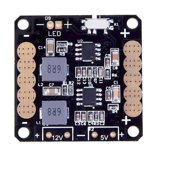
The PDB CC3D--BEC/ZMR is a specialized printed circuit board (PCB) designed for use with CC3D flight controllers, commonly utilized in drones and robotics applications. This power distribution board (PDB) simplifies the connection of multiple components, such as motors, sensors, and batteries, while providing regulated power through its built-in Battery Eliminator Circuit (BEC). Its compact design and robust functionality make it an essential component for building and maintaining multirotor drones and other robotic systems.
Explore Projects Built with pdb cc3d--bec/zmr
 Open Project in Cirkit Designer
 Open Project in Cirkit Designer
 Open Project in Cirkit Designer
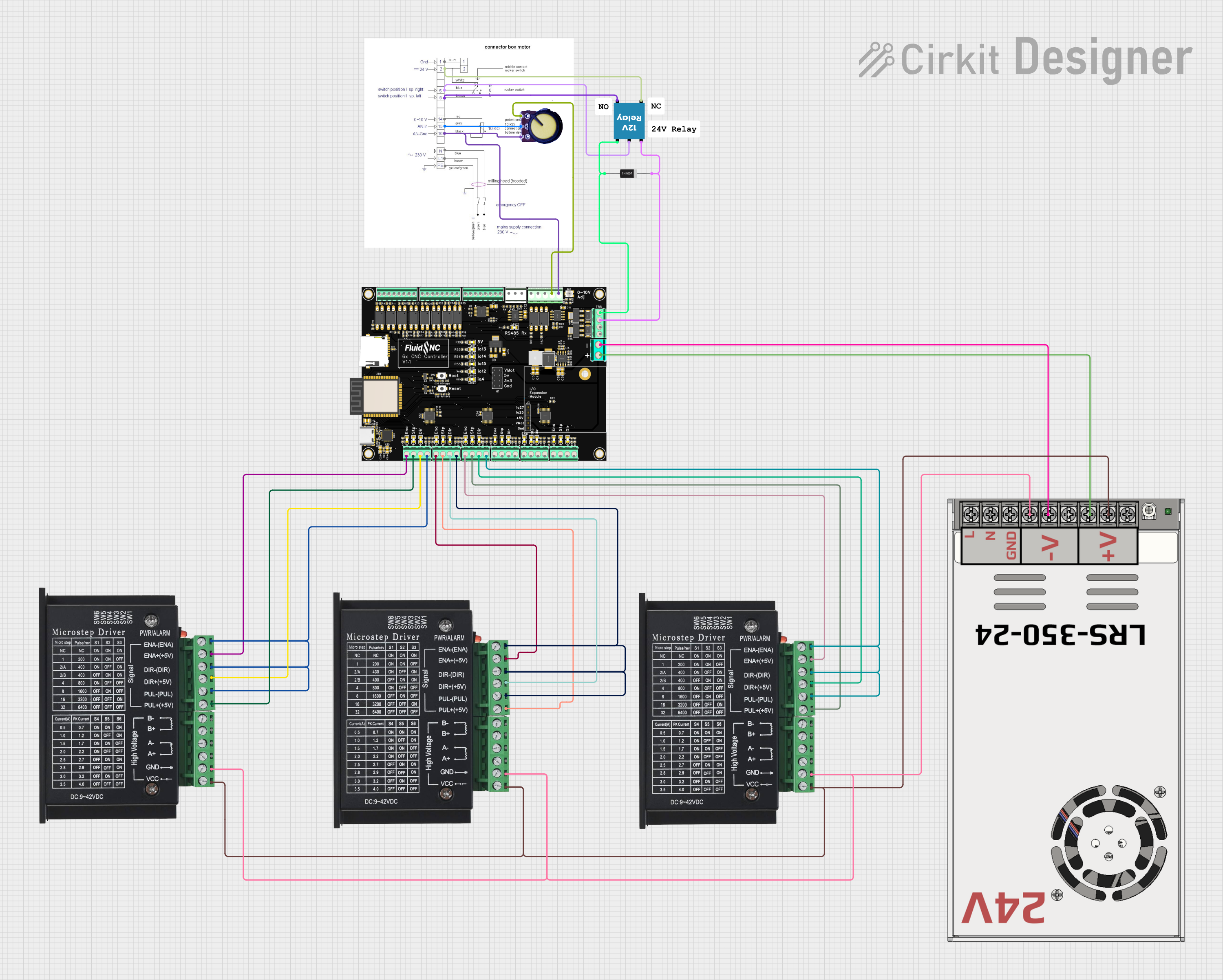 Open Project in Cirkit Designer
Explore Projects Built with pdb cc3d--bec/zmr
Open Project in Cirkit DesignerOpen Project in Cirkit DesignerOpen Project in Cirkit DesignerOpen Project in Cirkit DesignerCommon Applications and Use Cases
- Power distribution for quadcopters, hexacopters, and other multirotor drones.
- Integration with CC3D flight controllers for stable and efficient drone operation.
- Robotics projects requiring centralized power management for motors and sensors.
- DIY drone builds where compact and efficient power distribution is critical.
Technical Specifications
The PDB CC3D--BEC/ZMR is designed to handle high current loads while providing regulated power for flight controllers and other peripherals. Below are the key technical details:
General Specifications
| Parameter | Value |
|---|---|
| Input Voltage Range | 7V - 26V (2S to 6S LiPo) |
| Maximum Current Handling | 100A (total) |
| BEC Output Voltage | 5V and 12V |
| BEC Output Current | 3A (5V) / 3A (12V) |
| Dimensions | 36mm x 50mm |
| Weight | ~12g |
| PCB Material | FR4 (Flame Retardant) |
Pin Configuration and Descriptions
The PDB CC3D--BEC/ZMR features multiple solder pads and connectors for easy integration with other components. Below is the pin configuration:
Power Input and Output
| Pin/Pad Label | Description |
|---|---|
| BAT+ | Positive terminal for battery input |
| BAT- | Negative terminal for battery input |
| 5V | Regulated 5V output for peripherals |
| 12V | Regulated 12V output for peripherals |
| GND | Ground connection for all components |
Motor Connections
| Pad Label | Description |
|---|---|
| M1, M2, M3... | Motor power output pads (positive/negative pairs) |
Flight Controller Connections
| Pin/Pad Label | Description |
|---|---|
| FC+ | Positive power input for flight controller |
| FC- | Ground connection for flight controller |
Usage Instructions
How to Use the PDB CC3D--BEC/ZMR in a Circuit
- Power Input: Connect the battery's positive terminal to the
BAT+pad and the negative terminal to theBAT-pad. Ensure the battery voltage is within the supported range (7V - 26V). - Motor Connections: Solder the motor wires to the corresponding motor output pads (e.g.,
M1,M2, etc.). Ensure correct polarity for each motor. - Flight Controller Power: Connect the
FC+andFC-pads to the power input pins of the CC3D flight controller. - Peripheral Power: Use the
5Vand12Voutput pads to power additional components, such as sensors, cameras, or LEDs. - Grounding: Ensure all components share a common ground by connecting their ground wires to the
GNDpads on the PDB.
Important Considerations and Best Practices
- Soldering: Use high-quality solder and ensure all connections are secure to prevent power loss or short circuits.
- Heat Dissipation: Avoid overheating the PDB during soldering. Use a heat sink or fan if necessary.
- Current Limits: Do not exceed the maximum current rating (100A total) to prevent damage to the PDB.
- Voltage Compatibility: Verify that all connected components are compatible with the PDB's output voltages (5V and 12V).
- Insulation: Ensure the PDB is properly insulated to avoid short circuits with other components or the drone frame.
Example: Connecting to an Arduino UNO
While the PDB CC3D--BEC/ZMR is primarily designed for drones, it can also be used to power an Arduino UNO in robotics projects. Below is an example of how to connect the PDB to an Arduino UNO:
- Connect the
5Voutput pad on the PDB to the5Vpin on the Arduino UNO. - Connect a
GNDpad on the PDB to theGNDpin on the Arduino UNO. - Ensure the battery connected to the PDB is within the supported voltage range.
Sample Arduino Code
// Example code to control a motor using Arduino UNO and PDB CC3D--BEC/ZMR

const int motorPin = 9; // PWM pin connected to motor ESC signal wire

void setup() {
  pinMode(motorPin, OUTPUT); // Set motor pin as output
}

void loop() {
  // Gradually increase motor speed
  for (int speed = 0; speed <= 255; speed++) {
    analogWrite(motorPin, speed); // Send PWM signal to motor
    delay(20); // Wait 20ms before increasing speed
  }

  // Gradually decrease motor speed
  for (int speed = 255; speed >= 0; speed--) {
    analogWrite(motorPin, speed); // Send PWM signal to motor
    delay(20); // Wait 20ms before decreasing speed
  }
}
Troubleshooting and FAQs
Common Issues and Solutions
No Power Output:
- Cause: Loose or incorrect solder connections.
- Solution: Check all solder joints and ensure proper polarity for battery and components.
Overheating:
- Cause: Exceeding the maximum current rating or poor ventilation.
- Solution: Reduce the load on the PDB or improve airflow around the board.
Voltage Drop:
- Cause: High resistance in solder joints or wires.
- Solution: Use thicker wires and ensure solder joints are clean and secure.
Short Circuit:
- Cause: Exposed pads or wires touching each other.
- Solution: Inspect the PDB for shorts and use insulation where necessary.
FAQs
Q: Can I use this PDB with other flight controllers besides CC3D?
A: Yes, the PDB CC3D--BEC/ZMR is compatible with most flight controllers that require 5V or 12V power inputs.
Q: What type of battery should I use with this PDB?
A: The PDB supports 2S to 6S LiPo batteries (7V - 26V). Ensure the battery's capacity and discharge rate meet your drone's requirements.
Q: Can I power multiple peripherals simultaneously?
A: Yes, as long as the total current draw does not exceed the BEC's output current rating (3A for 5V and 3A for 12V).
Q: How do I secure the PDB to my drone frame?
A: Use nylon standoffs or double-sided adhesive tape to mount the PDB securely to the frame, ensuring it is insulated from conductive surfaces.