The Régulateur MPPT Epever 40A 12-24V de la série Tracer is a high-performance Maximum Power Point Tracking (MPPT) solar charge controller designed to maximize the energy harvested from solar panels. Manufactured by Epever, this device is capable of handling up to 40A of current and is compatible with both 12V and 24V battery systems. It ensures efficient energy conversion and battery charging, making it ideal for off-grid solar power systems.
Explore Projects Built with Régulateur MPPT Epever 40A 12-24V de la série Tracer
Use Cirkit Designer to design, explore, and prototype these projects online. Some projects support real-time simulation. Click "Open Project" to start designing instantly!
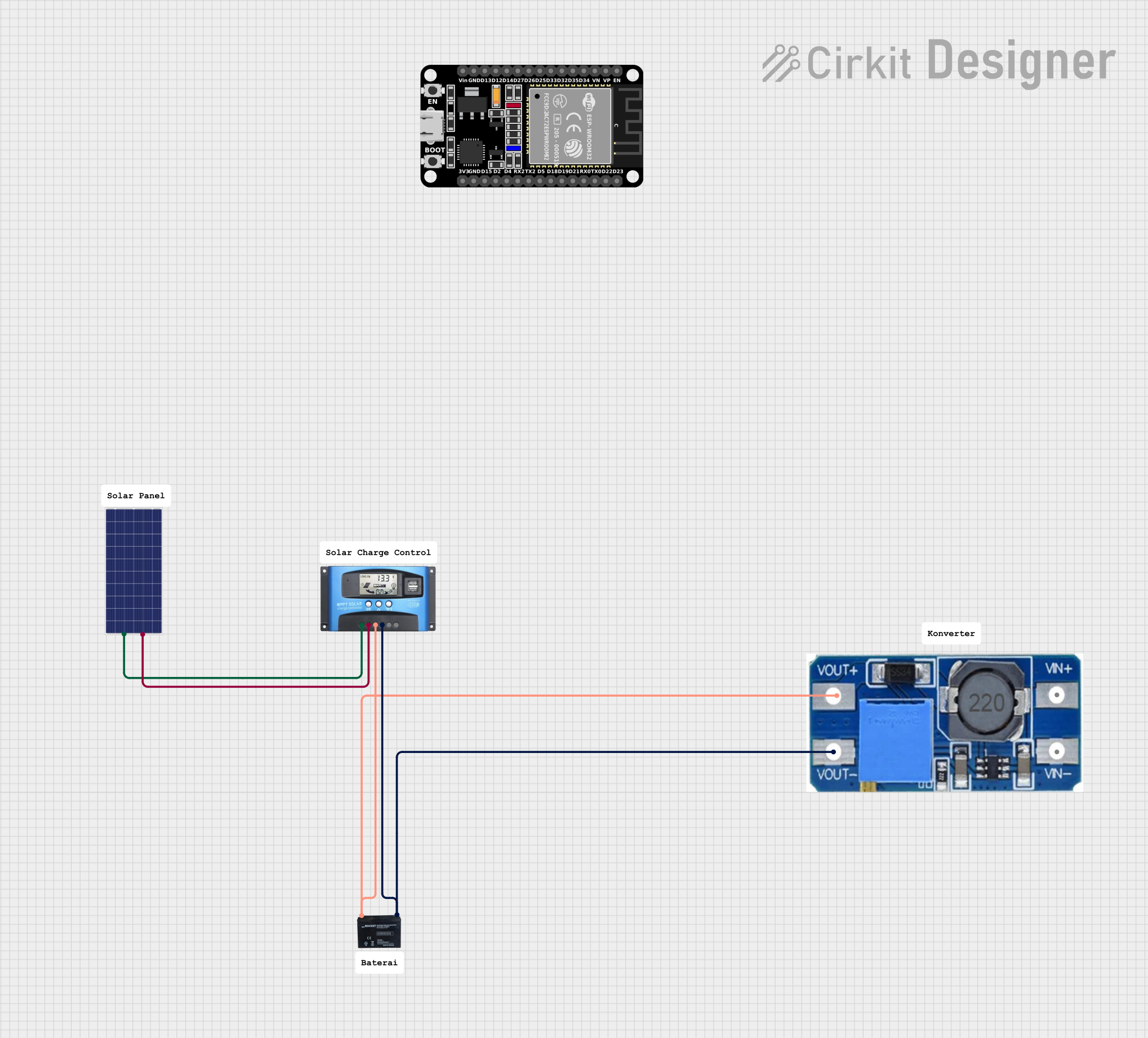
This circuit is a solar-powered battery charging system with an MPPT (Maximum Power Point Tracking) charge controller. The solar panel provides power to the MPPT SCC, which optimizes the charging of a 12V battery. A step-up boost converter is used to regulate the output voltage from the battery.
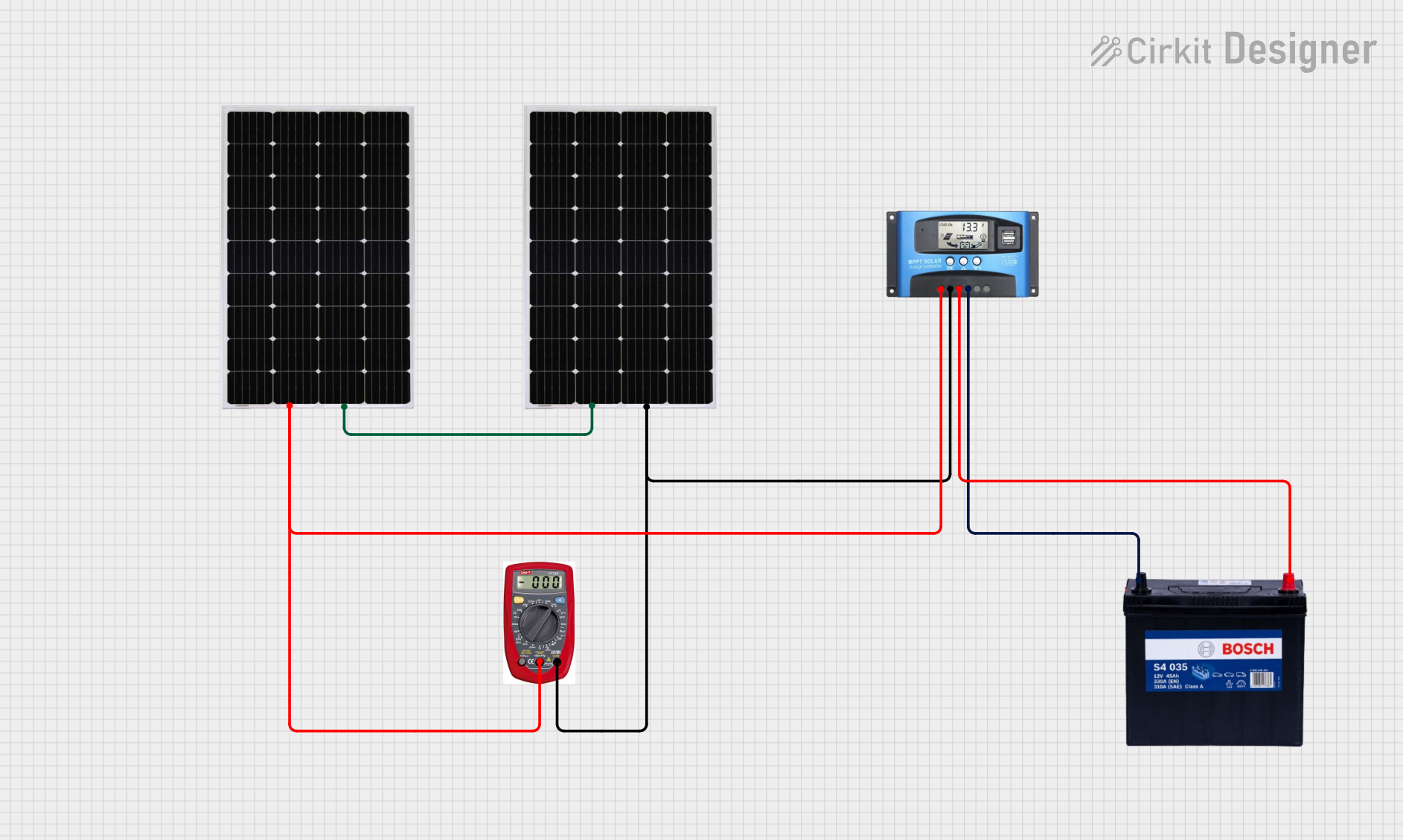
This circuit consists of two solar panels connected in series to an MPPT solar charge controller, which regulates the charging of a 12V 200Ah battery. A multimeter is integrated to monitor the voltage and current from the solar panels to the charge controller.
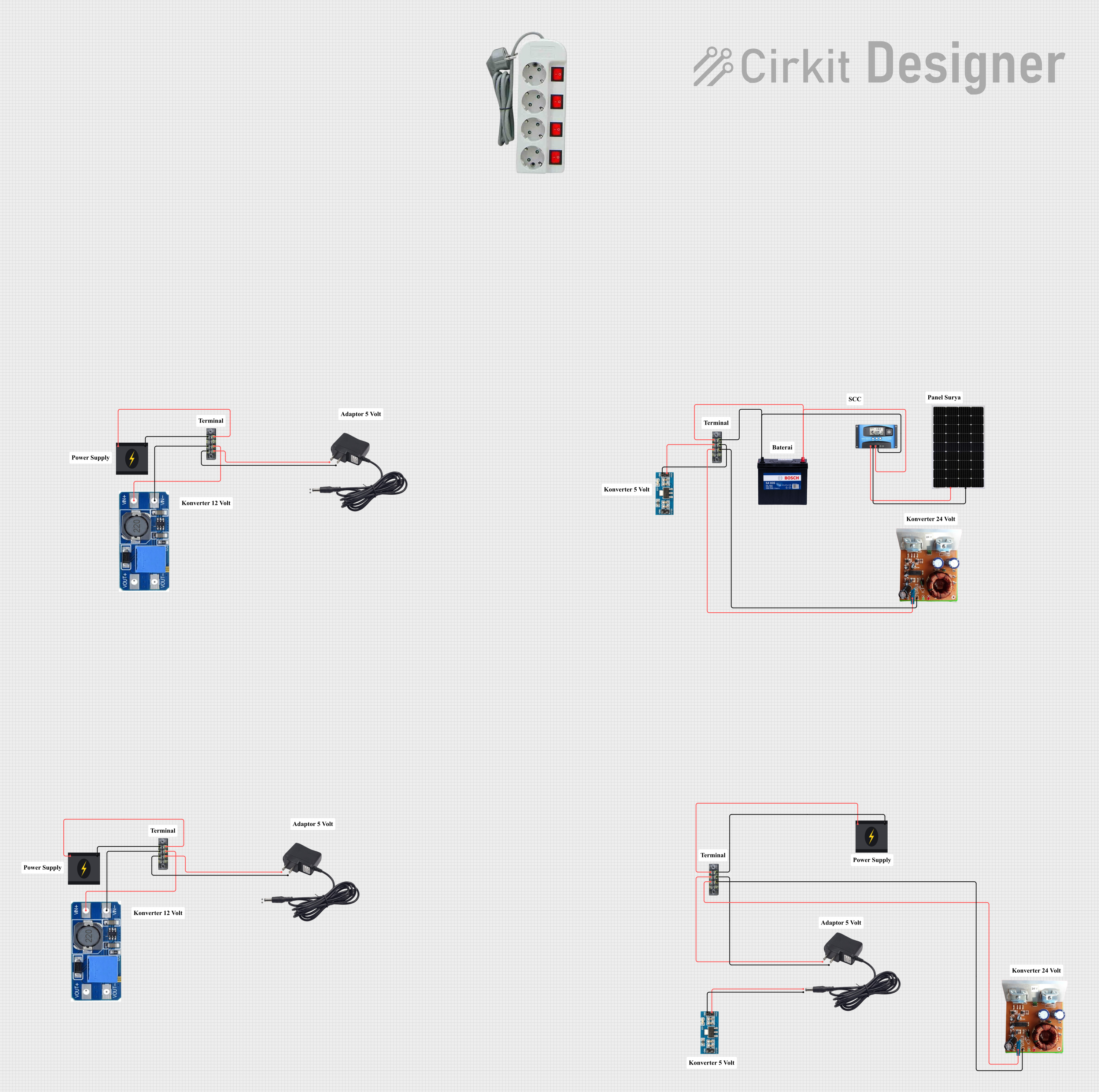
This circuit is a solar power management system that includes a solar panel, an MPPT solar charge controller, a 12V 200Ah battery, and various voltage converters. The system is designed to harness solar energy, store it in a battery, and provide regulated power outputs at different voltages for various loads.
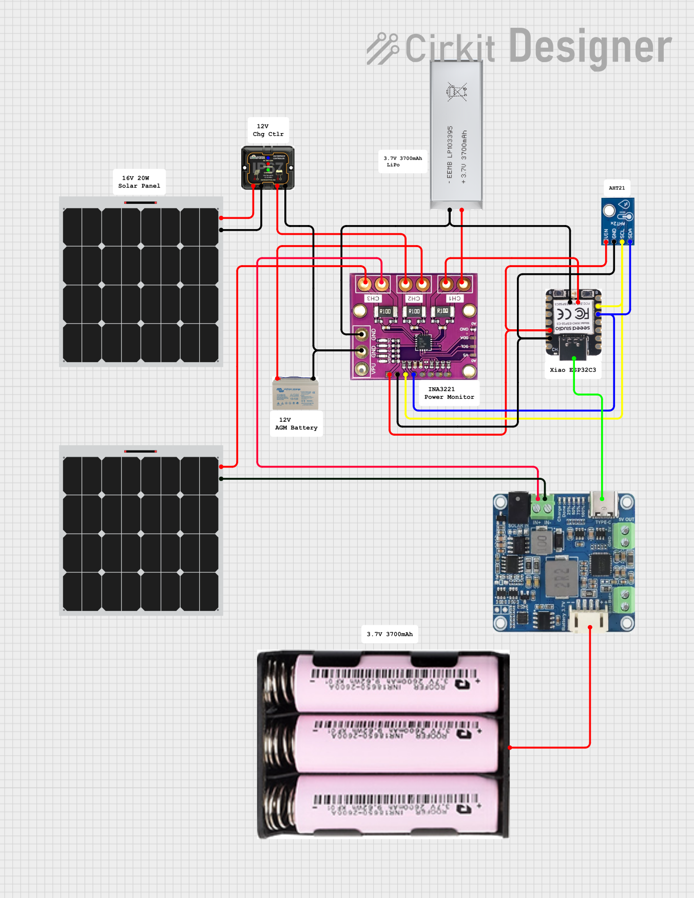
This circuit is designed for solar energy management and monitoring. It includes a 12V AGM battery charged by solar panels through an MPPT charge controller, with voltage monitoring provided by an INA3221 sensor. Additionally, a 3.7V battery is connected to an ESP32-C3 microcontroller and an AHT21 sensor for environmental data collection, with power management handled by a Waveshare Solar Manager.
Off-grid solar power systems for homes, cabins, and RVs
Solar-powered lighting systems
Battery charging for 12V or 24V systems
Renewable energy projects requiring efficient solar energy management
Technical Specifications
Below are the key technical details and pin configurations for the Régulateur MPPT Epever 40A:
Key Technical Details
Parameter
Specification
Manufacturer
Epever
Model
Tracer Series 40A
Input Voltage Range
12V/24V auto-recognition
Maximum Input Voltage
100V DC
Rated Charge Current
40A
Battery Voltage Range
8V to 32V
Efficiency
Up to 98%
Operating Temperature
-25°C to +45°C
Communication Interface
RS485 (Modbus protocol)
Dimensions
238 x 173 x 63.5 mm
Weight
2.4 kg
Pin Configuration and Descriptions
The Régulateur MPPT Epever 40A features several connection terminals for solar panels, batteries, and loads. Below is the pin configuration:
Pin/Terminal Label
Description
PV+ / PV-
Solar panel positive and negative terminals
BAT+ / BAT-
Battery positive and negative terminals
LOAD+ / LOAD-
Load positive and negative terminals
RS485
Communication port for monitoring and control
Temperature Sensor
Port for external temperature sensor
Remote Meter
Port for optional remote display unit
Usage Instructions
How to Use the Component in a Circuit
Connect the Solar Panel: Attach the positive (PV+) and negative (PV-) terminals of the solar panel to the corresponding inputs on the charge controller.
Connect the Battery: Connect the battery's positive (BAT+) and negative (BAT-) terminals to the charge controller. Ensure the battery voltage matches the system voltage (12V or 24V).
Connect the Load (Optional): If you wish to power a load directly, connect the load's positive (LOAD+) and negative (LOAD-) terminals to the charge controller.
Temperature Sensor (Optional): Plug in the external temperature sensor to enable temperature compensation for battery charging.
Monitor and Configure: Use the RS485 communication port to connect the controller to a PC or monitoring device. You can also use an optional remote meter for real-time monitoring.
Important Considerations and Best Practices
System Voltage: Ensure the battery and solar panel voltage are compatible with the controller's 12V/24V system.
Wiring: Use appropriately sized wires to handle the current and minimize voltage drops.
Fusing: Install fuses or circuit breakers between the solar panel, battery, and controller for safety.
Ventilation: Install the controller in a well-ventilated area to prevent overheating.
Firmware Updates: Check for firmware updates from Epever to ensure optimal performance.
Arduino UNO Integration Example
The Régulateur MPPT Epever 40A can be monitored using an Arduino UNO via the RS485 communication interface. Below is an example code snippet to read data from the controller:
#include <ModbusMaster.h>

// Instantiate ModbusMaster object
ModbusMaster node;

// Define RS485 communication pins
#define RE 2  // Receiver Enable pin
#define DE 3  // Driver Enable pin

void preTransmission() {
  digitalWrite(RE, HIGH); // Enable transmission
  digitalWrite(DE, HIGH);
}

void postTransmission() {
  digitalWrite(RE, LOW);  // Disable transmission
  digitalWrite(DE, LOW);
}

void setup() {
  Serial.begin(9600);       // Initialize serial communication
  node.begin(1, Serial);    // Set Modbus slave ID to 1
  pinMode(RE, OUTPUT);
  pinMode(DE, OUTPUT);
  node.preTransmission(preTransmission);
  node.postTransmission(postTransmission);
}

void loop() {
  uint8_t result;
  uint16_t data;

  // Read battery voltage (register 0x3100)
  result = node.readInputRegisters(0x3100, 1);
  if (result == node.ku8MBSuccess) {
    data = node.getResponseBuffer(0);
    Serial.print("Battery Voltage: ");
    Serial.print(data / 100.0); // Convert to volts
    Serial.println(" V");
  } else {
    Serial.println("Failed to read data");
  }

  delay(1000); // Wait 1 second before next read
}
Troubleshooting and FAQs
Common Issues Users Might Face
No Power Output:
Cause: Incorrect wiring or insufficient solar input.
Solution: Verify all connections and ensure the solar panel is receiving adequate sunlight.
Overheating:
Cause: Poor ventilation or excessive current.
Solution: Install the controller in a well-ventilated area and ensure the load does not exceed 40A.
Communication Failure:
Cause: Incorrect RS485 wiring or configuration.
Solution: Check the RS485 connections and ensure the correct Modbus slave ID is used.
Battery Not Charging:
Cause: Battery voltage mismatch or damaged battery.
Solution: Ensure the battery voltage matches the system voltage and test the battery for faults.
Solutions and Tips for Troubleshooting
Check LED Indicators: Refer to the user manual for LED status meanings to diagnose issues.
Use Monitoring Software: Utilize Epever's PC software or mobile app for detailed diagnostics.
Inspect Connections: Regularly check all wiring and terminals for loose or corroded connections.
Reset the Controller: If issues persist, reset the controller to factory settings and reconfigure.
By following this documentation, users can effectively install, operate, and troubleshoot the Régulateur MPPT Epever 40A 12-24V de la série Tracer for optimal solar energy management.


 Open Project in Cirkit Designer