How to Use STEPPERONLINE DM542T: Examples, Pinouts, and Specs
Introduction
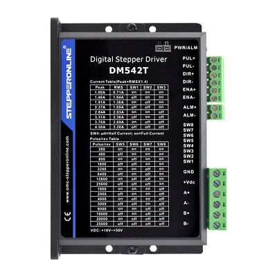
The STEPPERONLINE DM542T is a high-performance stepper motor driver designed to control a wide range of stepper motors with precision and efficiency. It is suitable for a variety of applications, including CNC machines, 3D printers, laser cutters, and robotics. The DM542T driver utilizes advanced microstepping technology to ensure smooth and accurate motor control, making it an ideal choice for projects that require precise positioning and smooth motion.
Explore Projects Built with STEPPERONLINE DM542T


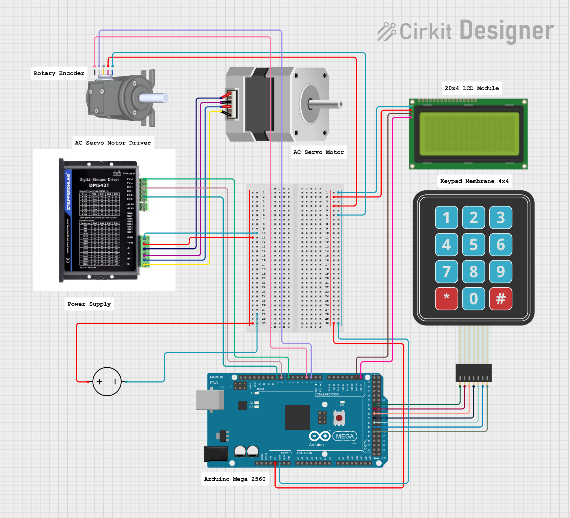
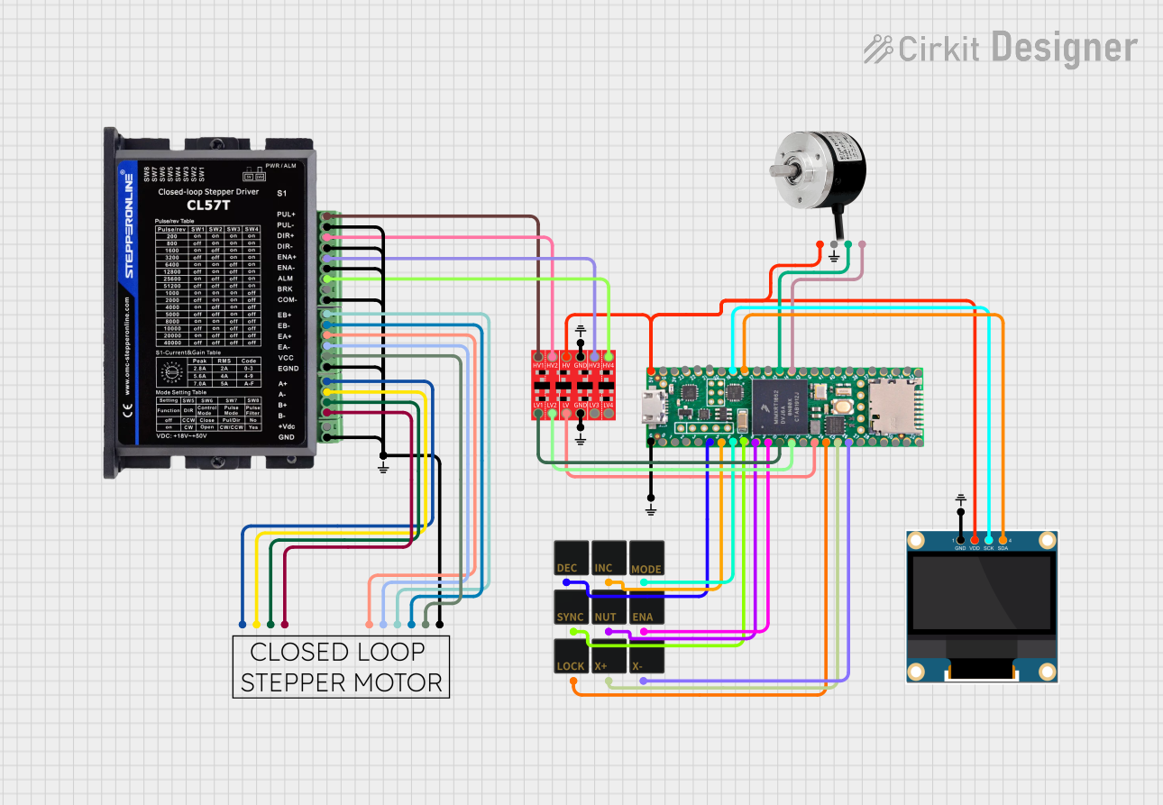
Explore Projects Built with STEPPERONLINE DM542T
Technical Specifications
Key Technical Details
- Supply Voltage: 20-50V DC
- Output Current: 1.0A - 4.2A (peak) adjustable
- Input Voltage: 5V DC (TTL compatible)
- Microstep Resolutions: Full, 1/2, 1/4, 1/8, 1/16, 1/32, 1/64, 1/128
- Pulse Input Frequency: Up to 200kHz
- Logic Signal Current: 7-16mA (Typical 10mA)
- Isolation Resistance: 500MΩ
Pin Configuration and Descriptions
| Pin Number | Signal Name | Description |
|---|---|---|
| PUL+ | Pulse Signal+ | Connect to pulse signal, 5V peak |
| PUL- | Pulse Signal- | Connect to negative of pulse signal |
| DIR+ | Direction Signal+ | Connect to direction signal, 5V peak |
| DIR- | Direction Signal- | Connect to negative of direction signal |
| ENA+ | Enable Signal+ | Connect to enable signal, 5V peak |
| ENA- | Enable Signal- | Connect to negative of enable signal |
| A+, A- | Motor Phase A | Connect to one coil of the stepper motor |
| B+, B- | Motor Phase B | Connect to the other coil of the stepper motor |
| VCC | Power Supply | Connect to 20-50V DC power supply |
| GND | Ground | Connect to power supply ground |
Usage Instructions
How to Use the Component in a Circuit
- Power Supply Connection: Connect the power supply to the VCC and GND pins, ensuring that the voltage is within the specified range (20-50V DC).
- Motor Connection: Connect the motor coils to the A+/A- and B+/B- terminals. Ensure that the connections are secure and that the motor specifications are compatible with the driver.
- Control Signal Connection: Connect the PUL+, PUL-, DIR+, DIR-, ENA+, and ENA- to the respective control signals. These signals typically come from a microcontroller or a CNC controller.
- Microstep Configuration: Set the microstep resolution by adjusting the onboard DIP switches according to the desired steps per revolution.
- Current Setting: Adjust the onboard potentiometer to set the output current to match the motor's rated current.
Important Considerations and Best Practices
- Always ensure the power supply is turned off before making any connections to prevent damage.
- Use appropriate heat sinking and ensure adequate ventilation around the driver to prevent overheating.
- Avoid running the motor driver at its maximum current rating for extended periods to prolong its lifespan.
- Ensure that the control signals are clean and free from noise to prevent erratic motor behavior.
Troubleshooting and FAQs
Common Issues and Solutions
- Motor Does Not Move: Check power supply, connections, and signal inputs. Ensure that the enable signal is active.
- Motor Vibrates but Does Not Rotate: Verify that the motor wires are connected correctly and that the microstep settings are appropriate for the application.
- Driver Overheating: Ensure proper heat sinking and airflow. Reduce the current setting if necessary.
FAQs
Q: Can the DM542T driver be used with any stepper motor? A: The DM542T can be used with a wide range of stepper motors as long as the motor's voltage and current requirements fall within the driver's specifications.
Q: How do I set the current limit on the DM542T? A: The current limit is set by adjusting the onboard potentiometer. Refer to the driver's manual for detailed instructions on setting the current limit.
Q: What is the maximum step frequency for the DM542T? A: The maximum step frequency for the DM542T is 200kHz.
Example Code for Arduino UNO
Below is an example code snippet for controlling a stepper motor using the DM542T driver with an Arduino UNO. This code assumes that the driver's PUL+, DIR+, and ENA+ are connected to the Arduino's digital pins and that the PUL-, DIR-, and ENA- are connected to the Arduino's GND.
// Define the connection pins
const int pulsePin = 2; // Connect to PUL+
const int dirPin = 3;   // Connect to DIR+
const int enablePin = 4; // Connect to ENA+

void setup() {
  // Set the pin modes
  pinMode(pulsePin, OUTPUT);
  pinMode(dirPin, OUTPUT);
  pinMode(enablePin, OUTPUT);

  // Disable the motor by setting enable pin high
  digitalWrite(enablePin, HIGH);
}

void loop() {
  // Enable the motor by setting enable pin low
  digitalWrite(enablePin, LOW);

  // Set the motor direction
  digitalWrite(dirPin, HIGH); // Set to LOW for the opposite direction

  // Pulse the motor for a number of steps
  for (int i = 0; i < 200; i++) {
    digitalWrite(pulsePin, HIGH);
    delayMicroseconds(500); // Adjust the speed by changing the delay
    digitalWrite(pulsePin, LOW);
    delayMicroseconds(500);
  }

  // Disable the motor
  digitalWrite(enablePin, HIGH);

  // Wait for a second
  delay(1000);
}
Remember to adjust the delayMicroseconds value to control the speed of the stepper motor. The example above will rotate the motor in one direction for 200 steps and then stop for a second before repeating the cycle.