
How to Use esp-12-D1: Examples, Pinouts, and Specs
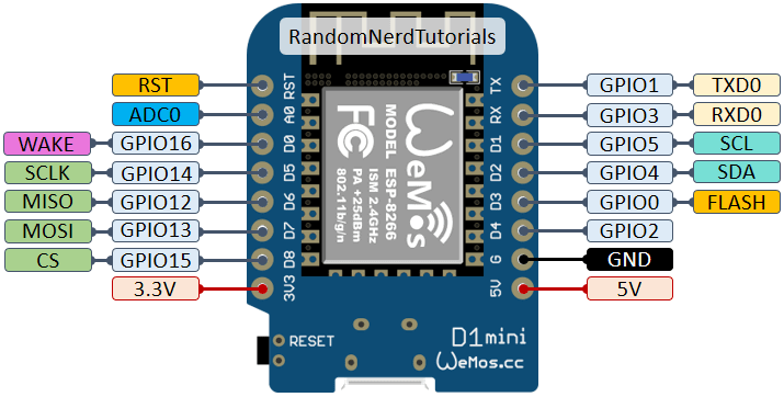
 Design with esp-12-D1 in Cirkit Designer
Introduction
The ESP-12-D1 is a Wi-Fi module manufactured by Guest, with the part ID esp-12_D1_note. It is based on the popular ESP8266 chip and is designed for seamless integration into Internet of Things (IoT) applications. This module features built-in Wi-Fi capabilities, multiple GPIO pins, and support for various communication protocols, making it a versatile choice for wireless connectivity in embedded systems.
Explore Projects Built with esp-12-D1
 Open Project in Cirkit Designer
 Open Project in Cirkit Designer
 Open Project in Cirkit Designer
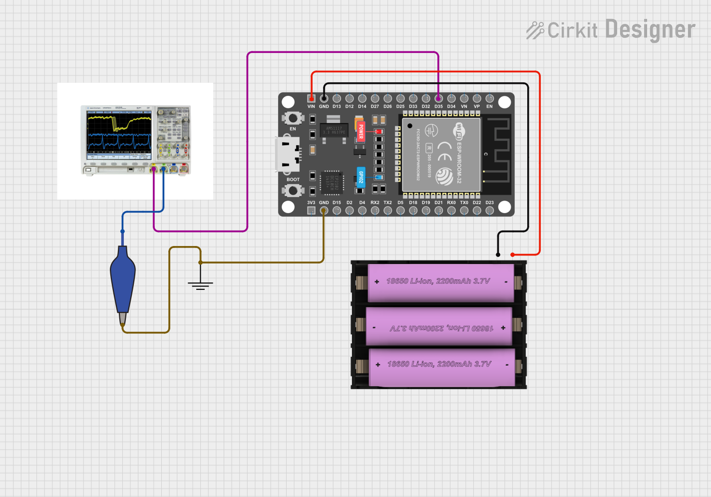 Open Project in Cirkit Designer
Explore Projects Built with esp-12-D1
Open Project in Cirkit DesignerOpen Project in Cirkit DesignerOpen Project in Cirkit DesignerOpen Project in Cirkit DesignerCommon Applications and Use Cases
- Smart home devices (e.g., smart lights, thermostats)
- IoT sensors and actuators
- Wireless data logging and monitoring
- Remote control systems
- Prototyping and development of Wi-Fi-enabled devices
Technical Specifications
The ESP-12-D1 module is packed with features that make it suitable for a wide range of applications. Below are its key technical specifications:
| Parameter | Value |
|---|---|
| Chipset | ESP8266 |
| Operating Voltage | 3.0V - 3.6V |
| Flash Memory | 4 MB |
| Wi-Fi Standards | 802.11 b/g/n |
| Frequency Range | 2.4 GHz |
| GPIO Pins | 11 |
| Communication Protocols | UART, SPI, I2C, PWM |
| Power Consumption | 80 mA (average), 200 mA (peak during TX) |
| Operating Temperature | -40°C to 125°C |
| Dimensions | 24 mm x 16 mm |
Pin Configuration and Descriptions
The ESP-12-D1 module has 16 pins, each serving a specific function. Below is the pinout and description:
| Pin Number | Pin Name | Function |
|---|---|---|
| 1 | GND | Ground |
| 2 | TXD | UART Transmit (TX) |
| 3 | RXD | UART Receive (RX) |
| 4 | GPIO0 | General Purpose I/O, Boot Mode Select |
| 5 | GPIO2 | General Purpose I/O |
| 6 | GPIO4 | General Purpose I/O |
| 7 | GPIO5 | General Purpose I/O |
| 8 | GPIO12 | General Purpose I/O |
| 9 | GPIO13 | General Purpose I/O |
| 10 | GPIO14 | General Purpose I/O |
| 11 | GPIO15 | General Purpose I/O, Boot Mode Select |
| 12 | GPIO16 | General Purpose I/O, Deep Sleep Wake |
| 13 | EN | Chip Enable (Active High) |
| 14 | VCC | Power Supply (3.3V) |
| 15 | ADC | Analog-to-Digital Converter Input |
| 16 | RST | Reset (Active Low) |
Usage Instructions
The ESP-12-D1 module is easy to integrate into circuits and can be programmed using platforms like Arduino IDE. Below are the steps to use the module effectively:
Connecting the ESP-12-D1 to an Arduino UNO
- Power Supply: Ensure the module is powered with 3.3V. Do not connect it directly to 5V as it may damage the module.
- UART Communication: Connect the TXD pin of the ESP-12-D1 to the RX pin of the Arduino UNO, and the RXD pin of the ESP-12-D1 to the TX pin of the Arduino UNO.
- GPIO Pins: Use the GPIO pins for interfacing with sensors, actuators, or other peripherals.
- Boot Mode: To upload code, connect GPIO0 to GND during boot. Disconnect it from GND after uploading.
Sample Code for Arduino IDE
Below is an example of how to connect the ESP-12-D1 to a Wi-Fi network using the Arduino IDE:
#include <ESP8266WiFi.h> // Include the ESP8266 Wi-Fi library

// Replace with your network credentials
const char* ssid = "Your_SSID";       // Wi-Fi network name
const char* password = "Your_PASSWORD"; // Wi-Fi network password

void setup() {
  Serial.begin(115200); // Initialize serial communication at 115200 baud
  WiFi.begin(ssid, password); // Start connecting to Wi-Fi

  Serial.print("Connecting to Wi-Fi");
  while (WiFi.status() != WL_CONNECTED) {
    delay(500); // Wait for connection
    Serial.print(".");
  }
  Serial.println("\nConnected to Wi-Fi!");
  Serial.print("IP Address: ");
  Serial.println(WiFi.localIP()); // Print the assigned IP address
}

void loop() {
  // Add your main code here
}
Important Considerations and Best Practices
- Voltage Levels: Always use a 3.3V power supply. If using a 5V system, use a voltage regulator or level shifter.
- Antenna Placement: Ensure the onboard antenna is not obstructed by metal objects to maintain good Wi-Fi signal strength.
- Deep Sleep Mode: Use GPIO16 to wake the module from deep sleep for power-saving applications.
- Firmware Updates: Keep the firmware updated to ensure compatibility and security.
Troubleshooting and FAQs
Common Issues and Solutions
Module Not Responding
- Cause: Incorrect wiring or insufficient power supply.
- Solution: Double-check the connections and ensure the module is powered with 3.3V.
Wi-Fi Connection Fails
- Cause: Incorrect SSID or password.
- Solution: Verify the credentials and ensure the Wi-Fi network is within range.
Code Upload Fails
- Cause: GPIO0 not connected to GND during boot.
- Solution: Connect GPIO0 to GND before powering the module and uploading the code.
Random Resets
- Cause: Power supply instability.
- Solution: Use a capacitor (e.g., 10 µF) across the VCC and GND pins to stabilize the power supply.
FAQs
Q: Can the ESP-12-D1 operate on 5V?
A: No, the ESP-12-D1 operates on 3.3V. Using 5V can damage the module.
Q: How do I reset the module?
A: Pull the RST pin low momentarily to reset the module.
Q: Can I use the ADC pin for analog sensors?
A: Yes, the ADC pin supports analog input, but it is limited to a maximum voltage of 1.0V. Use a voltage divider if needed.
Q: Is the ESP-12-D1 compatible with the Arduino IDE?
A: Yes, the ESP-12-D1 can be programmed using the Arduino IDE with the ESP8266 board package installed.
This concludes the documentation for the ESP-12-D1 module. For further assistance, refer to the manufacturer's datasheet or community forums.