How to Use r4 minima: Examples, Pinouts, and Specs
Introduction
The R4 Minima is a specialized resistor designed for electronic circuits where low resistance and compact size are critical. Its minimal physical footprint makes it ideal for modern, space-constrained designs. Additionally, the R4 Minima offers precise resistance values, ensuring reliable performance in applications requiring accurate current control.
Explore Projects Built with r4 minima
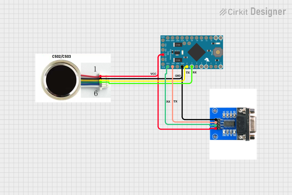
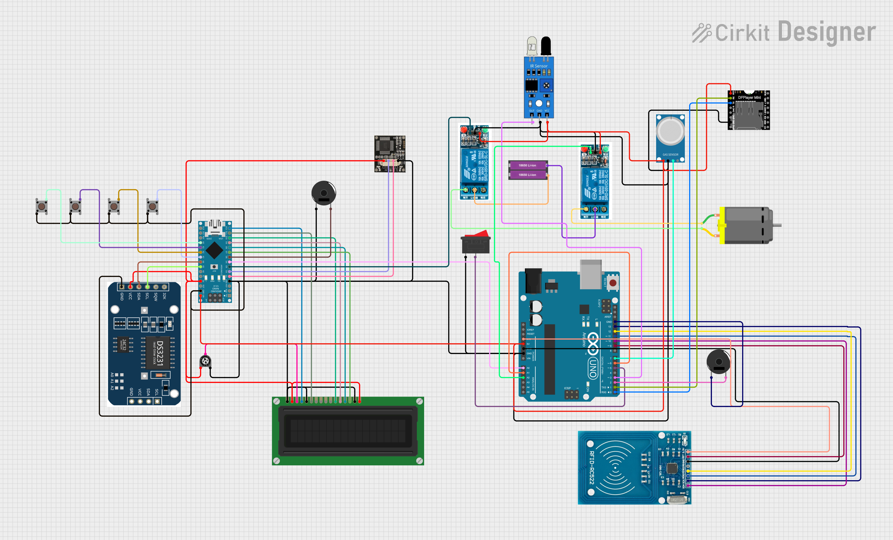
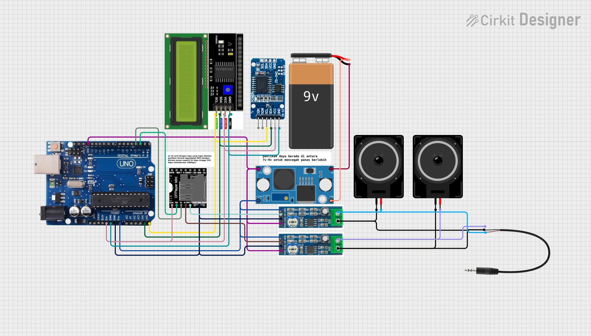

Explore Projects Built with r4 minima
Common Applications and Use Cases
- Compact electronic devices, such as smartphones and wearables
- Precision circuits for current sensing and voltage division
- High-density printed circuit boards (PCBs)
- Low-power applications where minimal heat dissipation is required
Technical Specifications
The R4 Minima resistor is engineered to meet the demands of modern electronics. Below are its key technical specifications:
| Parameter | Value |
|---|---|
| Resistance Range | 0.1 Ω to 10 Ω |
| Tolerance | ±1% (standard), ±0.5% (optional) |
| Power Rating | 0.125 W (1/8 W) |
| Temperature Coefficient | ±50 ppm/°C |
| Operating Temperature | -55°C to +125°C |
| Package Size | 0402, 0603 (SMD) |
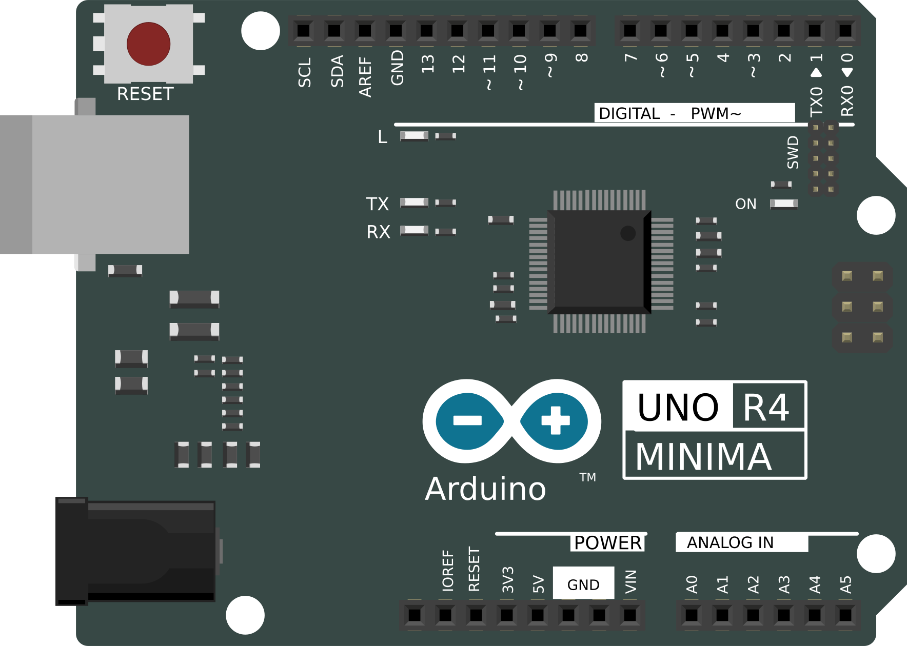
Pin Configuration and Descriptions
The R4 Minima is a two-terminal component with no polarity, making it straightforward to integrate into circuits. Below is a description of its terminals:
| Pin | Description |
|---|---|
| Pin 1 | Connects to one side of the circuit |
| Pin 2 | Connects to the other side of the circuit |
Usage Instructions
How to Use the R4 Minima in a Circuit
- Determine the Required Resistance Value: Use Ohm's Law (V = IR) to calculate the resistance needed for your application.
- Select the Correct Package Size: Choose between 0402 or 0603 based on your PCB design and space constraints.
- Soldering:
- Use a fine-tip soldering iron or reflow soldering for surface-mount installation.
- Ensure proper alignment of the resistor on the PCB pads.
- Verify Connections: After soldering, check the connections with a multimeter to ensure proper resistance and continuity.
Important Considerations and Best Practices
- Power Dissipation: Ensure the resistor's power rating (0.125 W) is not exceeded to avoid overheating or damage.
- Temperature Effects: Account for the temperature coefficient when designing circuits for environments with extreme temperature variations.
- Placement: Place the resistor as close as possible to the components it interacts with to minimize parasitic effects.
- Handling: Use ESD-safe tools when handling the R4 Minima to prevent damage from static electricity.
Example: Using R4 Minima with an Arduino UNO
The R4 Minima can be used in current-sensing applications with an Arduino UNO. Below is an example of how to measure current using the R4 Minima as a shunt resistor:
// Example: Current measurement using R4 Minima and Arduino UNO
// This code measures the voltage drop across the R4 Minima resistor
// to calculate the current flowing through it.

const int analogPin = A0; // Analog pin connected to the R4 Minima
const float resistorValue = 0.1; // Resistance of the R4 Minima in ohms

void setup() {
  Serial.begin(9600); // Initialize serial communication
}

void loop() {
  int sensorValue = analogRead(analogPin); // Read the analog voltage
  float voltage = sensorValue * (5.0 / 1023.0); // Convert to voltage
  float current = voltage / resistorValue; // Calculate current (I = V/R)

  // Print the current value to the Serial Monitor
  Serial.print("Current: ");
  Serial.print(current, 3); // Print current with 3 decimal places
  Serial.println(" A");

  delay(1000); // Wait for 1 second before the next reading
}
Troubleshooting and FAQs
Common Issues and Solutions
Incorrect Resistance Measurement:
- Cause: Poor soldering or damaged resistor.
- Solution: Recheck solder joints and verify the resistor's integrity with a multimeter.
Overheating:
- Cause: Exceeding the resistor's power rating.
- Solution: Ensure the power dissipation (P = I²R) is within the 0.125 W limit.
Inconsistent Readings in Circuits:
- Cause: Temperature variations or incorrect placement.
- Solution: Use resistors with a low temperature coefficient and place them close to related components.
FAQs
Q1: Can the R4 Minima be used in high-power applications?
A1: No, the R4 Minima is designed for low-power applications with a maximum power rating of 0.125 W.
Q2: Is the R4 Minima polarized?
A2: No, the R4 Minima is a non-polarized component and can be connected in either direction.
Q3: How do I choose the correct tolerance for my application?
A3: For precision circuits, use the ±0.5% tolerance variant. For general applications, the ±1% tolerance is sufficient.
Q4: Can I use the R4 Minima in high-frequency circuits?
A4: Yes, but ensure proper placement and minimal lead inductance to avoid parasitic effects.