How to Use ESP32-WROOM-32 (36 PIN): Examples, Pinouts, and Specs
Introduction
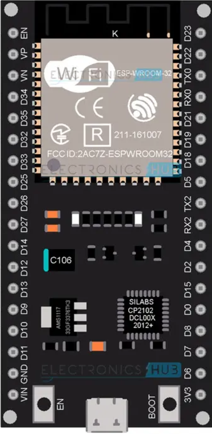
The ESP32-WROOM-32 (36 PIN) is a powerful Wi-Fi and Bluetooth microcontroller module developed by Espressif. It is based on the ESP32 dual-core processor and is designed for a wide range of IoT applications. With its integrated wireless capabilities, extensive GPIO options, and robust processing power, the ESP32-WROOM-32 is ideal for projects requiring connectivity, real-time processing, and low power consumption.
Explore Projects Built with ESP32-WROOM-32 (36 PIN)


Explore Projects Built with ESP32-WROOM-32 (36 PIN)
Common Applications and Use Cases
- IoT devices and smart home automation
- Wireless sensor networks
- Wearable electronics
- Industrial automation
- Robotics and drones
- Prototyping and development of connected devices
Technical Specifications
Key Technical Details
- Manufacturer: Espressif
- Part ID: DEVKIT V1
- Processor: Dual-core Xtensa® 32-bit LX6 CPU
- Clock Speed: Up to 240 MHz
- Wireless Connectivity: Wi-Fi 802.11 b/g/n and Bluetooth v4.2 (Classic + BLE)
- Flash Memory: 4 MB (default, expandable)
- SRAM: 520 KB
- Operating Voltage: 3.3V
- Input Voltage Range: 5V (via USB) or 7-12V (via VIN pin)
- GPIO Pins: 34 (multipurpose, including ADC, DAC, PWM, I2C, SPI, UART)
- ADC Channels: 18 (12-bit resolution)
- DAC Channels: 2
- PWM Channels: 16
- Operating Temperature: -40°C to +85°C
- Dimensions: 25.5 mm x 51 mm
Pin Configuration and Descriptions
The ESP32-WROOM-32 (36 PIN) module features a total of 36 pins. Below is the pinout and description:
| Pin Number | Pin Name | Function |
|---|---|---|
| 1 | EN | Enable pin. Active high to enable the module. |
| 2 | IO0 | GPIO0. Used for boot mode selection during programming. |
| 3 | IO1 (TX0) | GPIO1. UART0 TX pin. |
| 4 | IO3 (RX0) | GPIO3. UART0 RX pin. |
| 5 | IO4 | GPIO4. General-purpose I/O. |
| 6 | IO5 | GPIO5. General-purpose I/O. |
| 7 | IO12 | GPIO12. Can be used as ADC, touch, or general-purpose I/O. |
| 8 | IO13 | GPIO13. Can be used as ADC, touch, or general-purpose I/O. |
| 9 | IO14 | GPIO14. Can be used as ADC, touch, or general-purpose I/O. |
| 10 | IO15 | GPIO15. Can be used as ADC, touch, or general-purpose I/O. |
| 11 | IO16 | GPIO16. General-purpose I/O. |
| 12 | IO17 | GPIO17. General-purpose I/O. |
| 13 | IO18 | GPIO18. SPI clock (SCK) or general-purpose I/O. |
| 14 | IO19 | GPIO19. SPI MISO or general-purpose I/O. |
| 15 | IO21 | GPIO21. I2C SDA or general-purpose I/O. |
| 16 | IO22 | GPIO22. I2C SCL or general-purpose I/O. |
| 17 | IO23 | GPIO23. SPI MOSI or general-purpose I/O. |
| 18 | IO25 | GPIO25. DAC1 or general-purpose I/O. |
| 19 | IO26 | GPIO26. DAC2 or general-purpose I/O. |
| 20 | IO27 | GPIO27. General-purpose I/O. |
| 21 | IO32 | GPIO32. ADC or general-purpose I/O. |
| 22 | IO33 | GPIO33. ADC or general-purpose I/O. |
| 23 | IO34 | GPIO34. ADC input only. |
| 24 | IO35 | GPIO35. ADC input only. |
| 25 | GND | Ground. |
| 26 | 3V3 | 3.3V power output. |
| 27 | VIN | Input voltage (7-12V). |
| 28 | TX2 | UART2 TX pin. |
| 29 | RX2 | UART2 RX pin. |
| 30 | TX1 | UART1 TX pin. |
| 31 | RX1 | UART1 RX pin. |
| 32 | BOOT | Boot mode selection pin. |
| 33 | RST | Reset pin. Active low to reset the module. |
| 34 | IO36 | GPIO36. ADC input only. |
| 35 | IO39 | GPIO39. ADC input only. |
| 36 | NC | Not connected. |
Usage Instructions
How to Use the ESP32-WROOM-32 in a Circuit
Powering the Module:
- Use the VIN pin to supply 7-12V or connect a 5V USB power source.
- Ensure the 3.3V pin is not overloaded, as it is for low-power peripherals only.
Programming the Module:
- Connect the ESP32 to your computer via a USB cable.
- Install the necessary drivers (e.g., CP2102 or CH340, depending on your board).
- Use the Arduino IDE or Espressif's ESP-IDF for programming.
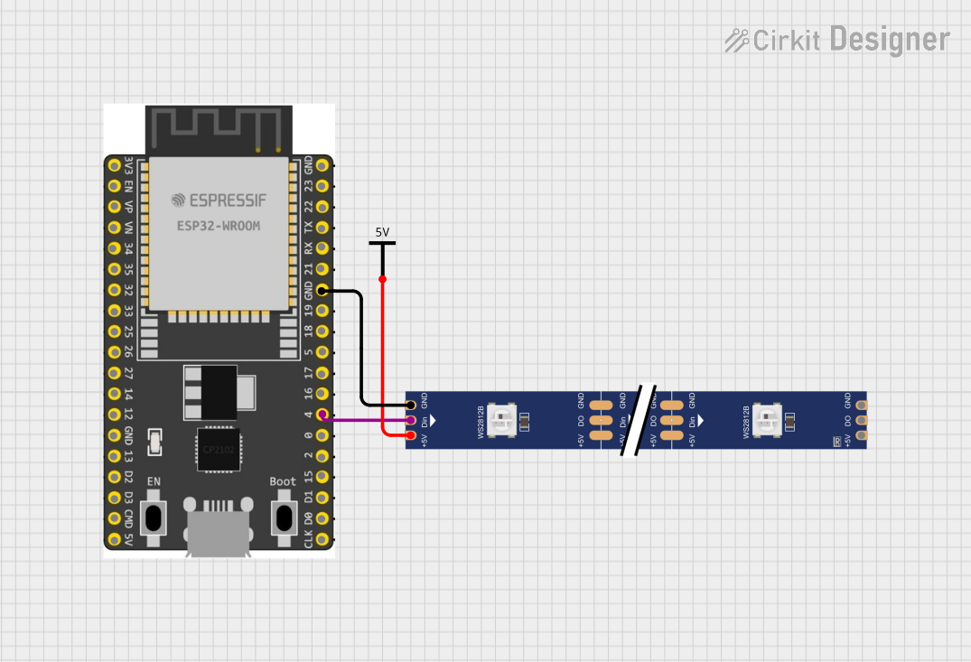
Connecting Peripherals:
- Use GPIO pins for connecting sensors, actuators, or other peripherals.
- Configure the pins in your code as input, output, or alternate functions (e.g., ADC, PWM).
Flashing Code:
- Hold the BOOT button while pressing the EN button to enter programming mode.
- Upload your code using the Arduino IDE or other compatible tools.
Important Considerations and Best Practices
- Avoid applying more than 3.3V to GPIO pins to prevent damage.
- Use level shifters when interfacing with 5V devices.
- Ensure proper grounding to avoid noise and instability in the circuit.
- Use decoupling capacitors near the power pins for stable operation.
Example Code for Arduino UNO
Below is an example of how to blink an LED connected to GPIO2:
// Define the GPIO pin for the LED
#define LED_PIN 2

void setup() {
  // Set the LED pin as an output
  pinMode(LED_PIN, OUTPUT);
}

void loop() {
  // Turn the LED on
  digitalWrite(LED_PIN, HIGH);
  delay(1000); // Wait for 1 second

  // Turn the LED off
  digitalWrite(LED_PIN, LOW);
  delay(1000); // Wait for 1 second
}
Troubleshooting and FAQs
Common Issues and Solutions
ESP32 Not Detected by Computer:
- Ensure the correct USB drivers (CP2102 or CH340) are installed.
- Try a different USB cable or port.
Code Upload Fails:
- Check the COM port in the Arduino IDE.
- Hold the BOOT button while pressing the EN button during upload.
Wi-Fi Connection Issues:
- Verify the SSID and password in your code.
- Ensure the router is within range and supports 2.4 GHz Wi-Fi.
GPIO Pin Not Working:
- Check if the pin is configured correctly in the code.
- Avoid using reserved pins (e.g., GPIO6-GPIO11 for flash memory).
FAQs
Q: Can the ESP32-WROOM-32 operate on battery power?
- A: Yes, it can be powered using a LiPo battery connected to the VIN pin.
Q: How do I reset the ESP32?
- A: Press the RST button or pull the RST pin low.
Q: Can I use the ESP32 with 5V logic?
- A: No, the ESP32 operates on 3.3V logic. Use level shifters for 5V devices.