How to Use HX711 (left-facing): Examples, Pinouts, and Specs
Introduction
The HX711 is a precision 24-bit analog-to-digital converter (ADC) designed for applications requiring high accuracy and low noise, such as weigh scales and industrial control systems. It is specifically optimized for reading load cells and other bridge sensors, making it a popular choice in electronic weighing systems. The left-facing orientation refers to the direction of the input pins, which can be important for certain circuit layouts and designs.
Explore Projects Built with HX711 (left-facing)
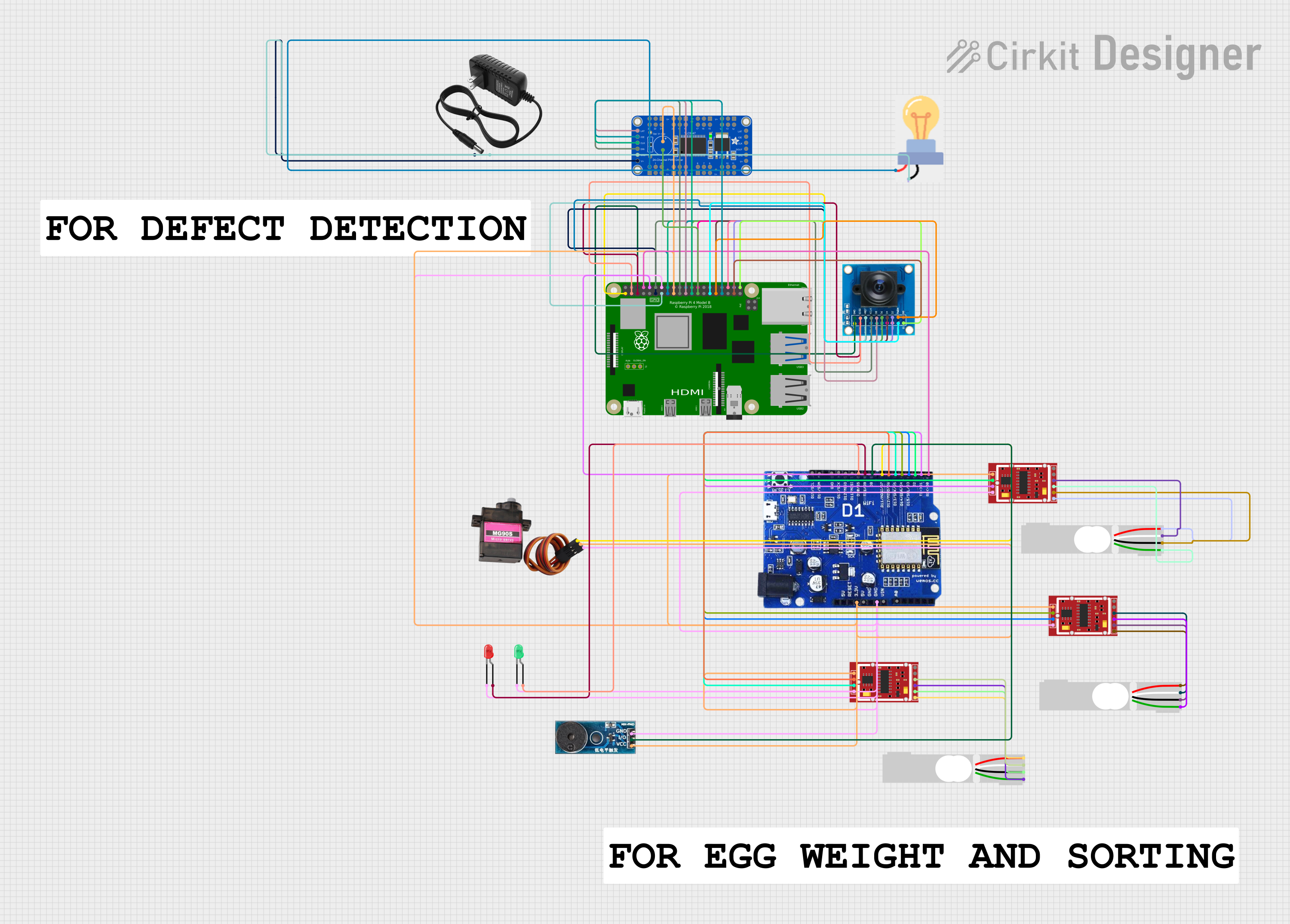
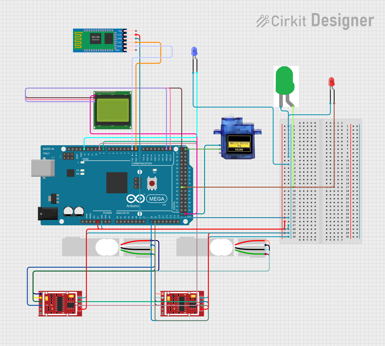
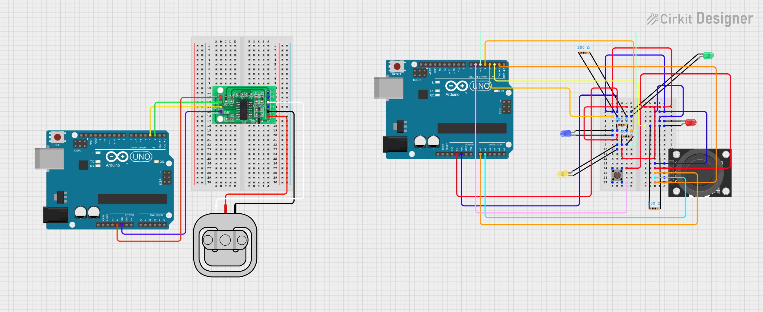
Explore Projects Built with HX711 (left-facing)
Common Applications:
- Digital weigh scales
- Industrial process control
- Load cell signal amplification
- Force and pressure measurement systems
Technical Specifications
The HX711 is a highly integrated ADC with an internal amplifier, designed to interface directly with bridge sensors. Below are its key technical details:
Key Specifications:
- Resolution: 24-bit ADC
- Input Channels: 2 differential input channels (Channel A and Channel B)
- Gain: Programmable gain of 32, 64, or 128 (default: 128 for Channel A)
- Operating Voltage: 2.6V to 5.5V
- Current Consumption: < 1.5mA (normal mode), < 1µA (power-down mode)
- Data Rate: 10Hz or 80Hz (selectable)
- Temperature Range: -40°C to +85°C
- Input Noise: < 1µV (at gain = 128, 10Hz data rate)
- Interface: Serial (2-wire: Data and Clock)
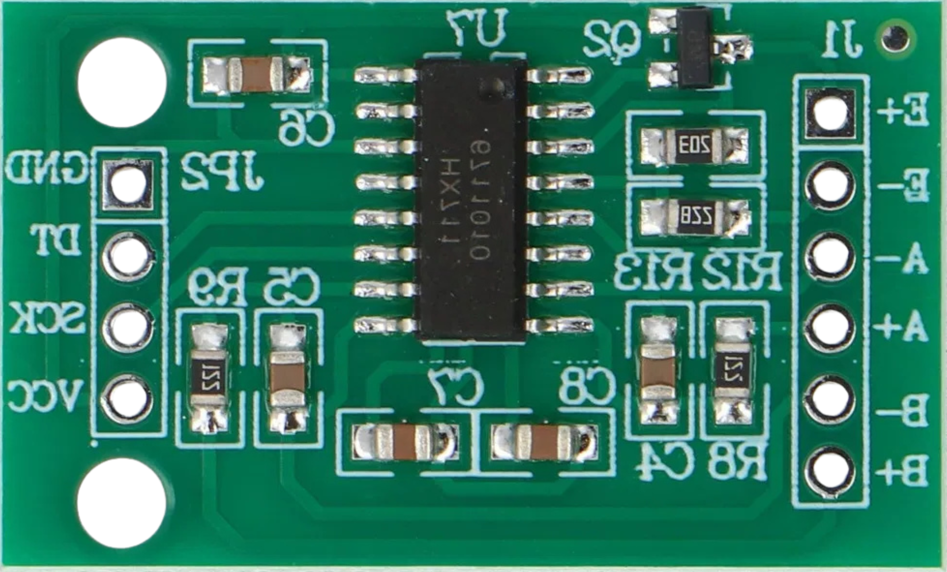
Pin Configuration:
The HX711 has 16 pins, but only 10 are typically used in most applications. Below is the pinout for the left-facing orientation:
| Pin Number | Pin Name | Description |
|---|---|---|
| 1 | VCC | Power supply (2.6V to 5.5V) |
| 2 | VFB | Feedback voltage for internal regulator (connect to VCC for external supply) |
| 3 | VBG | Bandgap reference voltage (not typically used in standard applications) |
| 4 | AVDD | Analog power supply (connect to VCC) |
| 5 | AGND | Analog ground |
| 6 | A+ | Positive input for Channel A |
| 7 | A- | Negative input for Channel A |
| 8 | B+ | Positive input for Channel B |
| 9 | B- | Negative input for Channel B |
| 10 | DGND | Digital ground |
| 11 | PD_SCK | Power-down and serial clock input |
| 12 | DOUT | Serial data output |
| 13-16 | NC | Not connected |
Usage Instructions
The HX711 is straightforward to use in a circuit, especially for load cell applications. Below are the steps and considerations for integrating the HX711 into your project:
Connecting the HX711:
- Power Supply: Connect the VCC pin to a 3.3V or 5V power source, and connect AGND and DGND to ground.
- Load Cell Connection:
- Connect the load cell's positive signal wire to A+ and the negative signal wire to A-.
- If using a second load cell or sensor, connect it to B+ and B-.
- Microcontroller Interface:
- Connect the PD_SCK pin to a digital output pin on your microcontroller (e.g., Arduino).
- Connect the DOUT pin to a digital input pin on your microcontroller.
Important Considerations:
- Gain Selection: The gain is set automatically based on the input channel:
- Channel A: Gain = 128 or 64
- Channel B: Gain = 32
- Data Rate: The data rate is selectable between 10Hz and 80Hz by controlling the PD_SCK pin during initialization.
- Decoupling Capacitors: Place a 0.1µF capacitor between VCC and GND to reduce noise.
Example Code for Arduino UNO:
Below is an example of how to interface the HX711 with an Arduino UNO to read data from a load cell:
#include "HX711.h" // Include the HX711 library

// Define HX711 pins
#define DOUT 3  // Data output pin connected to Arduino pin 3
#define CLK 2   // Clock pin connected to Arduino pin 2

HX711 scale; // Create an instance of the HX711 class

void setup() {
  Serial.begin(9600); // Initialize serial communication
  scale.begin(DOUT, CLK); // Initialize the HX711 with the defined pins
  scale.set_scale(); // Set the scale factor (calibration required)
  scale.tare(); // Reset the scale to zero
  Serial.println("HX711 initialized. Place weight on the scale.");
}

void loop() {
  if (scale.is_ready()) { // Check if the HX711 is ready
    long reading = scale.get_units(); // Get the weight reading
    Serial.print("Weight: ");
    Serial.print(reading);
    Serial.println(" units");
  } else {
    Serial.println("HX711 not ready. Check connections.");
  }
  delay(500); // Wait 500ms before the next reading
}
Notes:
- The
HX711.hlibrary can be installed via the Arduino Library Manager. - Calibration is required to convert raw ADC values into meaningful weight units.
Troubleshooting and FAQs
Common Issues:
No Data Output:
- Cause: Incorrect wiring or loose connections.
- Solution: Double-check all connections, especially the DOUT and PD_SCK pins.
Unstable Readings:
- Cause: Electrical noise or insufficient power supply decoupling.
- Solution: Add a 0.1µF capacitor between VCC and GND. Ensure a stable power source.
Incorrect Weight Measurements:
- Cause: Improper calibration or incorrect gain setting.
- Solution: Perform proper calibration using known weights. Verify the gain setting.
HX711 Not Ready:
- Cause: Faulty sensor or incorrect initialization.
- Solution: Check the load cell connections and ensure the HX711 is powered correctly.
FAQs:
Q: Can I use the HX711 with a 3.3V microcontroller?
- A: Yes, the HX711 operates at 2.6V to 5.5V, making it compatible with 3.3V systems.
Q: How do I calibrate the HX711?
- A: Use a known weight to determine the scale factor. Adjust the scale factor in your code using the
set_scale()function.
- A: Use a known weight to determine the scale factor. Adjust the scale factor in your code using the
Q: Can I connect multiple load cells to the HX711?
- A: Yes, the HX711 supports two channels (A and B). However, only one channel can be read at a time.
Q: What is the difference between the left-facing and right-facing HX711?
- A: The orientation refers to the direction of the input pins, which may affect circuit layout but does not impact functionality.