How to Use ProtoSnap - Pro Mini: Examples, Pinouts, and Specs
Introduction
The ProtoSnap - Pro Mini is an innovative prototyping solution that combines a variety of electronic components on a single, compact protoboard. At the heart of this platform is an Arduino-compatible Pro Mini microcontroller, which allows users to program and control the integrated components with ease. This makes the ProtoSnap - Pro Mini an ideal choice for hobbyists, educators, and prototyping professionals who require a quick and efficient way to develop and test their ideas.
Common applications of the ProtoSnap - Pro Mini include:
- Rapid prototyping of electronic circuits
- Educational projects for learning electronics and programming
- Development of wearable technology
- IoT device creation
- Small-scale automation projects
Explore Projects Built with ProtoSnap - Pro Mini

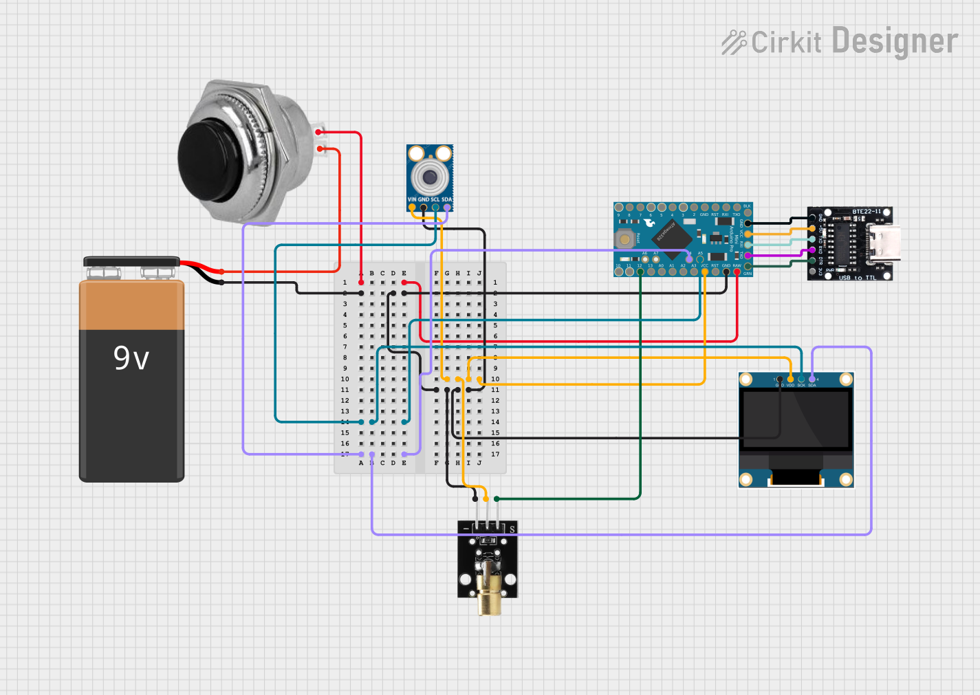
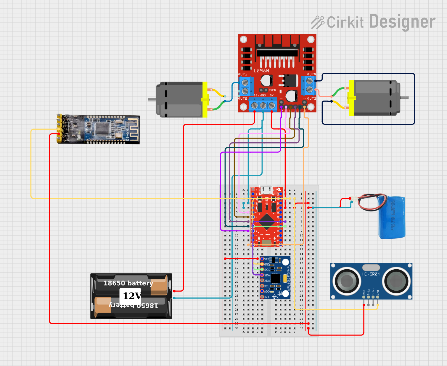
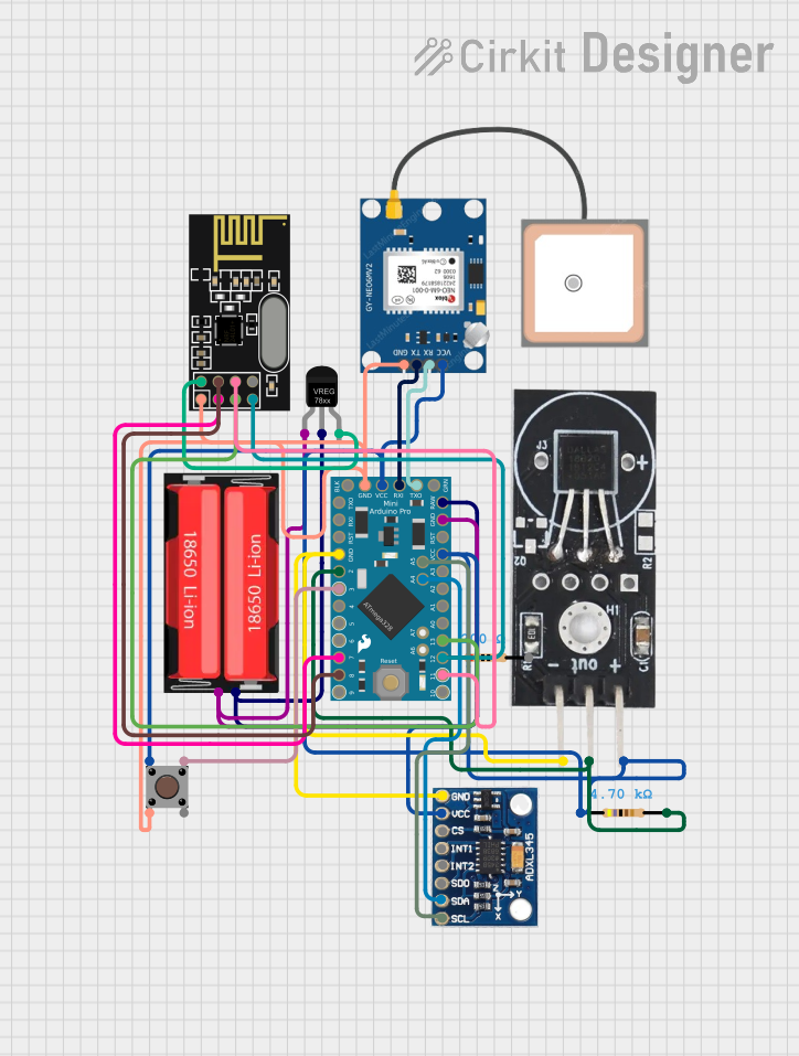
Explore Projects Built with ProtoSnap - Pro Mini
Technical Specifications
Key Technical Details
- Microcontroller: ATmega328
- Operating Voltage: 3.3V or 5V (depending on the model)
- Input Voltage: 3.35-12V (3.3V model) or 5-12V (5V model)
- Digital I/O Pins: 14 (of which 6 provide PWM output)
- Analog Input Pins: 8
- DC Current per I/O Pin: 40 mA
- Flash Memory: 32 KB (ATmega328) of which 0.5 KB used by bootloader
- SRAM: 2 KB (ATmega328)
- EEPROM: 1 KB (ATmega328)
- Clock Speed: 8 MHz (3.3V model) or 16 MHz (5V model)
Pin Configuration and Descriptions
| Pin Number | Function | Description |
|---|---|---|
| 1 | RESET | Used to reset the microcontroller |
| 2-13 | Digital Pins | Digital input/output pins, PWM on pins 3, 5, 6, 9, 10, and 11 |
| 14-21 | Analog Pins | Analog input pins A0-A7 |
| 22 | AREF | Analog reference voltage for the ADC |
| 23 | GND | Ground |
| 24 | RST | Reset pin, can be used to externally reset the microcontroller |
| 25 | VCC | Positive supply voltage for the microcontroller |
| 26 | GND | Ground |
| 27 | RAW | Raw voltage input for onboard voltage regulator |
| 28 | GND | Ground |
| 29 | RXI | Receive data (serial communication) |
| 30 | TXO | Transmit data (serial communication) |
| 31 | GND | Ground |
| 32 | BLK | Blocked, reserved for future use |
Usage Instructions
Integrating the ProtoSnap - Pro Mini into a Circuit
- Powering the Board: Connect a power supply to the RAW and GND pins if using an unregulated power source, or to the VCC and GND pins if using a regulated 3.3V or 5V supply.
- Programming the Board: Use a USB-to-serial breakout board or cable to connect the RXI and TXO pins to your computer for programming the Pro Mini via the Arduino IDE.
- Using Digital and Analog Pins: Connect sensors, actuators, and other components to the digital and analog pins as required for your project. Ensure that the connected devices are compatible with the operating voltage of the Pro Mini.
- Resetting the Board: If necessary, the RESET pin can be used to manually reset the microcontroller.
Important Considerations and Best Practices
- Always verify the power supply voltage and current ratings before connecting to the ProtoSnap - Pro Mini to prevent damage.
- When connecting components to the I/O pins, ensure that the total current does not exceed the maximum rating for each pin and for the microcontroller as a whole.
- Use pull-up or pull-down resistors with digital inputs to ensure a stable state when switches or sensors are disconnected.
- Avoid placing the board in environments with extreme temperatures, humidity, or where it may be subjected to mechanical stress.
Troubleshooting and FAQs
Common Issues
Q: Why is my ProtoSnap - Pro Mini not responding to the uploaded sketch? A: Ensure that the correct board and port are selected in the Arduino IDE. Check the wiring, especially the USB-to-serial connections, and verify that the correct drivers are installed.
Q: How can I reset the Pro Mini if it's not responding? A: Briefly connect the RESET pin to GND to manually reset the microcontroller.
Q: I'm having trouble with serial communication, what should I do? A: Check the baud rate settings and ensure that the RXI and TXO pins are correctly connected. Also, make sure that no other devices are using the same serial port.
Solutions and Tips for Troubleshooting
- Double-check all connections and ensure that they are secure and correct.
- Use a multimeter to verify voltages at different points in the circuit.
- If you encounter unexpected behavior, simplify your setup to isolate the issue.
- Consult the Arduino community forums and the manufacturer's support resources for additional assistance.
Example Code for Arduino UNO
// Blink an LED connected to pin 13 of the ProtoSnap - Pro Mini

void setup() {
  pinMode(13, OUTPUT); // Set pin 13 as an output
}

void loop() {
  digitalWrite(13, HIGH); // Turn the LED on
  delay(1000);            // Wait for a second
  digitalWrite(13, LOW);  // Turn the LED off
  delay(1000);            // Wait for a second
}
Note: This example assumes that an LED is connected to pin 13 with a suitable current-limiting resistor. Always ensure that the components you connect are rated for the voltage and current supplied by the ProtoSnap - Pro Mini pins.