
How to Use Arduino Can-Bus Shield: Examples, Pinouts, and Specs
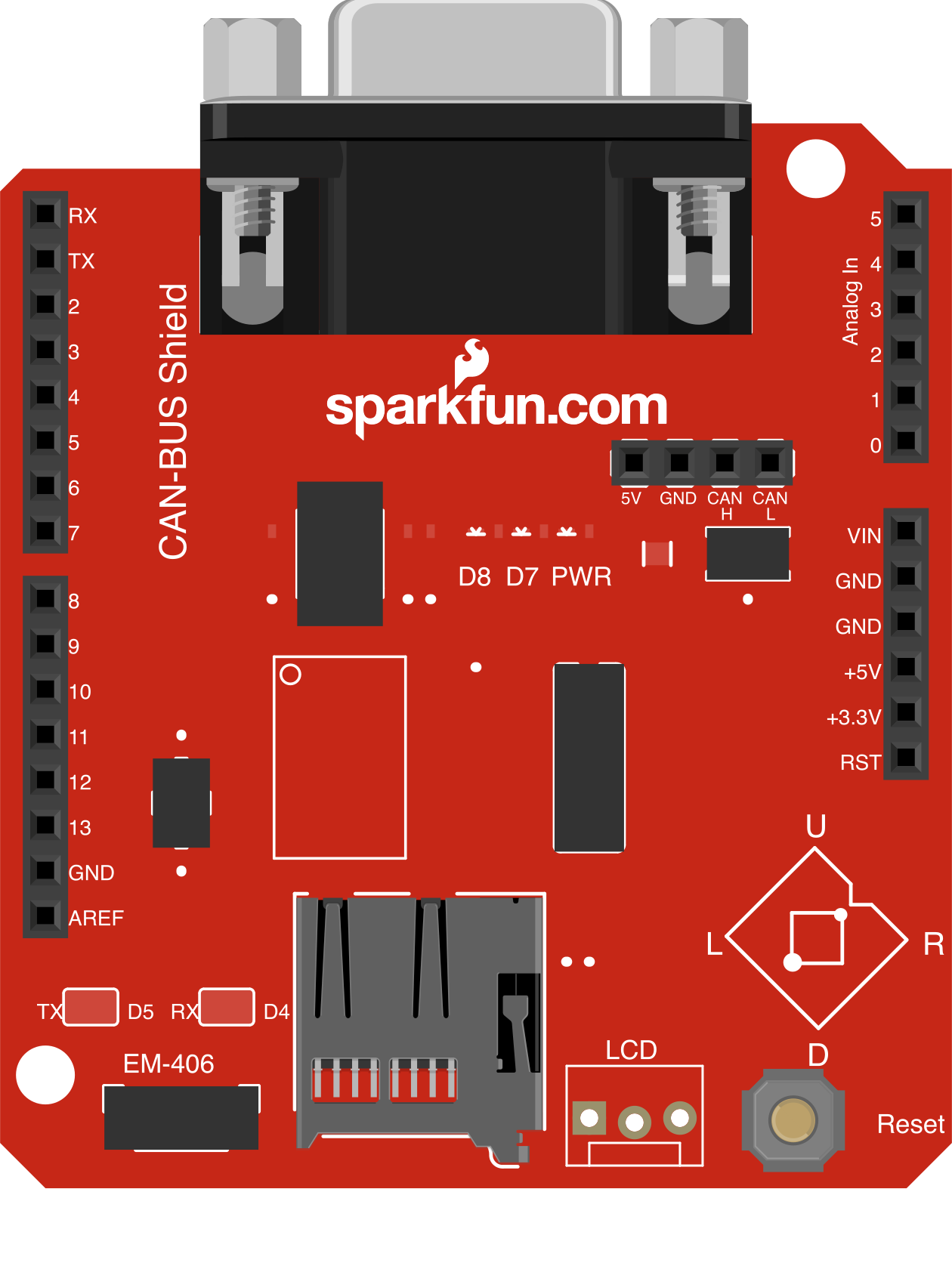
 Design with Arduino Can-Bus Shield in Cirkit Designer
Introduction
The Arduino CAN-Bus Shield (Manufacturer Part ID: DEV-10039) by SparkFun Electronics is a versatile shield designed to enable Arduino boards to communicate using the Controller Area Network (CAN) protocol. CAN is a robust communication standard widely used in automotive, industrial, and embedded systems for reliable data exchange between microcontrollers and devices.
This shield is ideal for applications such as:
- Automotive diagnostics and data logging
- Industrial automation and control systems
- Robotics and sensor networks
- Communication between multiple microcontrollers
The shield is built around the MCP2515 CAN controller and the MCP2551 CAN transceiver, providing a complete solution for CAN communication.
Explore Projects Built with Arduino Can-Bus Shield
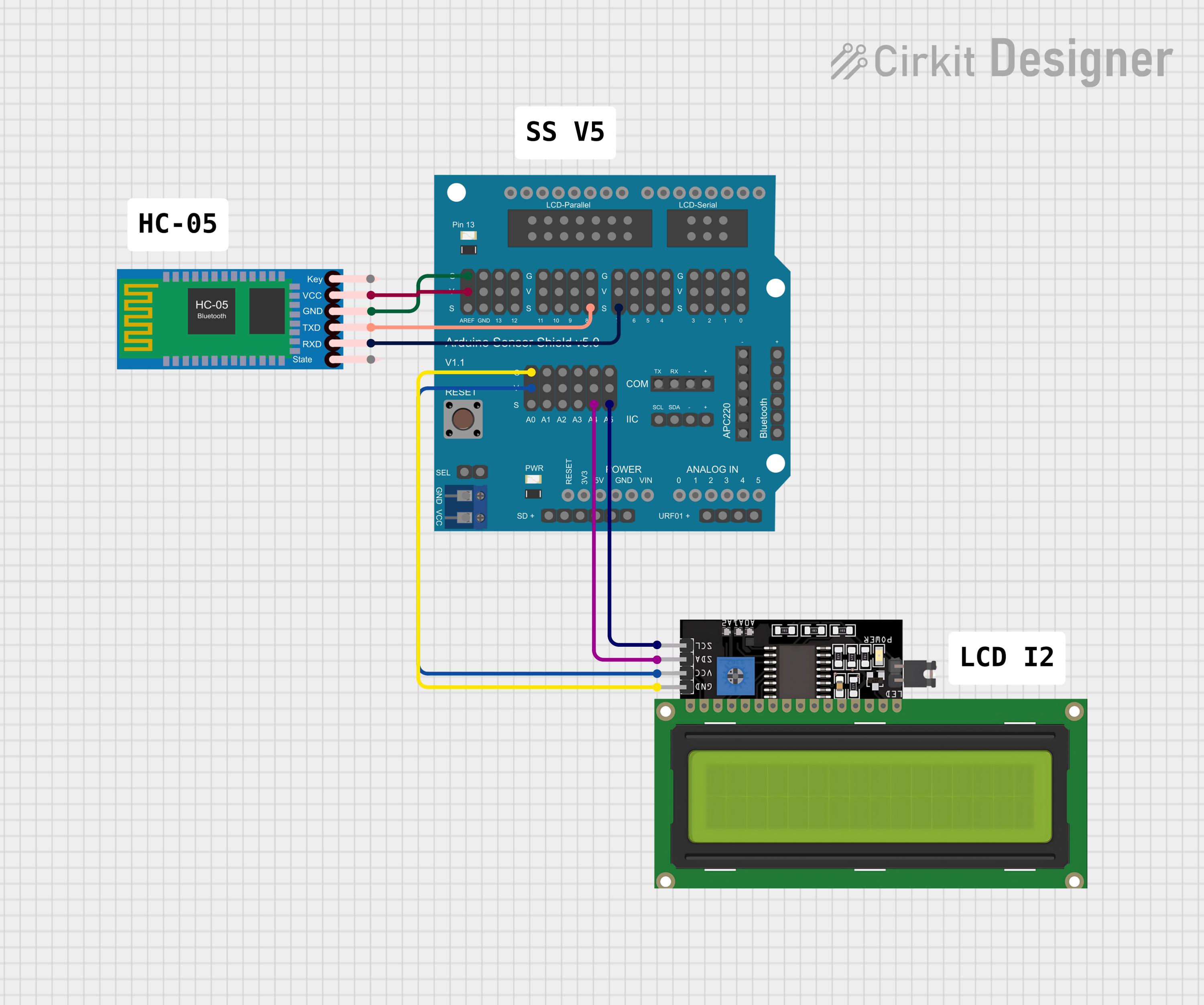 Open Project in Cirkit Designer
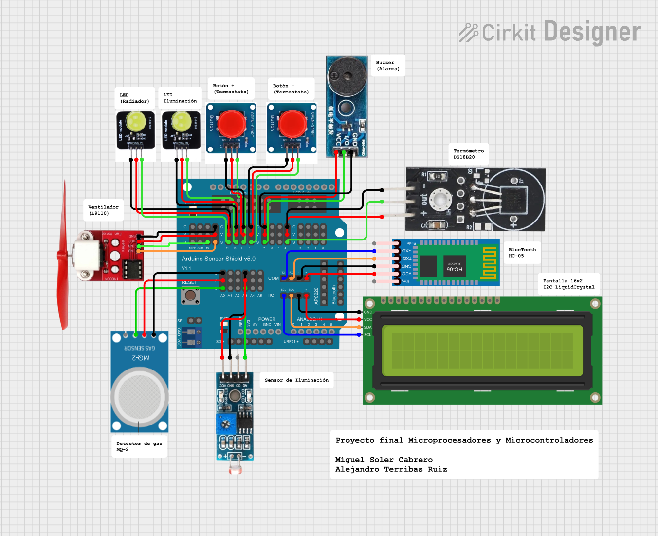 Open Project in Cirkit Designer
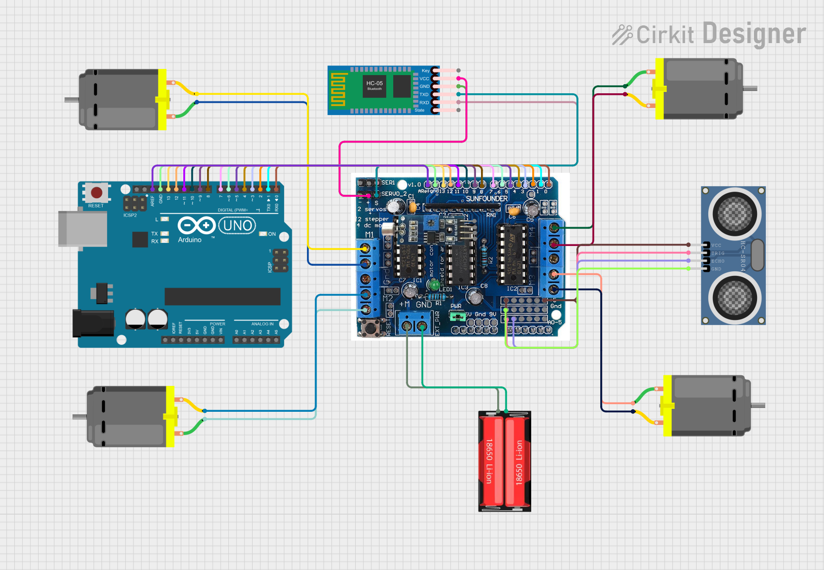 Open Project in Cirkit Designer
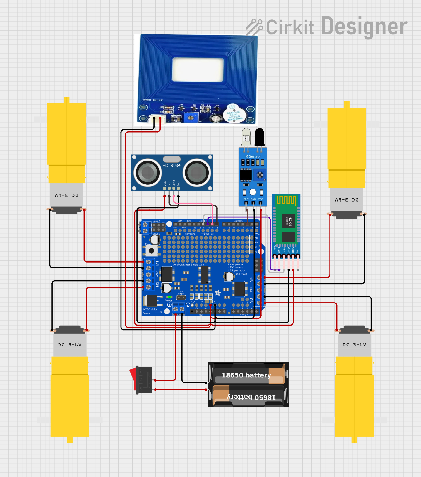 Open Project in Cirkit Designer
Explore Projects Built with Arduino Can-Bus Shield
Open Project in Cirkit DesignerOpen Project in Cirkit DesignerOpen Project in Cirkit DesignerOpen Project in Cirkit DesignerTechnical Specifications
Key Technical Details
| Parameter | Specification |
|---|---|
| Operating Voltage | 5V (supplied by the Arduino board) |
| CAN Controller | MCP2515 (SPI interface) |
| CAN Transceiver | MCP2551 |
| Communication Protocol | CAN 2.0B (up to 1 Mbps) |
| SPI Clock Speed | Up to 10 MHz |
| Operating Temperature | -40°C to +85°C |
| Dimensions | Standard Arduino shield size |
| Additional Features | SD card slot, serial LCD connector, and LEDs |
Pin Configuration and Descriptions
The Arduino CAN-Bus Shield connects to the Arduino board via the standard shield headers. Below is the pin configuration:
| Pin on Shield | Function | Description |
|---|---|---|
| D10 | SPI Chip Select (CS) | Selects the MCP2515 CAN controller |
| D11 | SPI MOSI | Master Out Slave In for SPI communication |
| D12 | SPI MISO | Master In Slave Out for SPI communication |
| D13 | SPI Clock (SCK) | Clock signal for SPI communication |
| D2 | CAN Interrupt (INT) | Interrupt pin for MCP2515 |
| GND | Ground | Common ground connection |
| 5V | Power Supply | Supplies power to the shield |
Usage Instructions
How to Use the Shield in a Circuit
- Attach the Shield: Plug the CAN-Bus Shield onto your Arduino board, ensuring proper alignment of the headers.
- Connect to a CAN Network: Use the DB9 connector or screw terminals to connect the shield to a CAN bus. Ensure proper termination resistance (120Ω) is present on the bus.
- Install Required Libraries: Download and install the MCP_CAN library from the Arduino Library Manager or GitHub. This library provides functions to initialize the CAN controller, send, and receive messages.
- Write Your Code: Use the library functions to configure the CAN bus speed, send messages, and process received data.
Example Code for Arduino UNO
Below is an example sketch to send a CAN message using the shield:
#include <mcp_can.h>
#include <SPI.h>

// Define the SPI Chip Select pin for the MCP2515
#define CAN_CS_PIN 10

// Create an instance of the MCP_CAN class
MCP_CAN CAN(CAN_CS_PIN);

void setup() {
  Serial.begin(115200); // Initialize serial communication for debugging
  while (!Serial);

  // Initialize the CAN controller at 500 kbps
  if (CAN.begin(MCP_ANY, 500000, MCP_8MHZ) == CAN_OK) {
    Serial.println("CAN-Bus Shield initialized successfully!");
  } else {
    Serial.println("Error initializing CAN-Bus Shield. Check connections.");
    while (1);
  }

  // Set the CAN controller to normal mode
  CAN.setMode(MCP_NORMAL);
  Serial.println("CAN controller set to normal mode.");
}

void loop() {
  // Define a sample CAN message
  unsigned char message[8] = {0x01, 0x02, 0x03, 0x04, 0x05, 0x06, 0x07, 0x08};

  // Send the CAN message with ID 0x100
  if (CAN.sendMsgBuf(0x100, 0, 8, message) == CAN_OK) {
    Serial.println("Message sent successfully!");
  } else {
    Serial.println("Error sending message.");
  }

  delay(1000); // Wait 1 second before sending the next message
}
Important Considerations and Best Practices
- Termination Resistor: Ensure the CAN bus is properly terminated with 120Ω resistors at both ends of the bus.
- Power Supply: The shield draws power from the Arduino board. Ensure the Arduino's power supply can handle the additional load.
- CAN Bus Speed: Match the CAN bus speed with other devices on the network.
- Error Handling: Implement error handling in your code to manage communication issues.
Troubleshooting and FAQs
Common Issues and Solutions
| Issue | Possible Cause | Solution |
|---|---|---|
| Shield not initializing | Incorrect wiring or loose connections | Check all connections and ensure proper alignment of the shield. |
| No messages received | Incorrect CAN bus speed | Verify and match the CAN bus speed with other devices. |
| Error sending messages | Bus not terminated properly | Ensure 120Ω termination resistors are present at both ends of the CAN bus. |
| Arduino not powering the shield | Insufficient power supply | Use a reliable power source for the Arduino board. |
FAQs
Can I use this shield with boards other than Arduino UNO?
- Yes, the shield is compatible with most Arduino boards, including the Mega and Leonardo. Ensure the SPI pins match the board's configuration.
What is the maximum CAN bus speed supported?
- The shield supports speeds up to 1 Mbps, but ensure all devices on the bus support the same speed.
Can I use the SD card slot and CAN communication simultaneously?
- Yes, but ensure proper SPI management in your code to avoid conflicts.
How do I monitor CAN messages on a PC?
- Use a USB-to-CAN adapter or a similar tool to connect the CAN bus to your computer for monitoring.
By following this documentation, you can effectively integrate the SparkFun Arduino CAN-Bus Shield into your projects for reliable CAN communication.