How to Use Sparkfun 9DOF Breakout Board: Examples, Pinouts, and Specs
Introduction
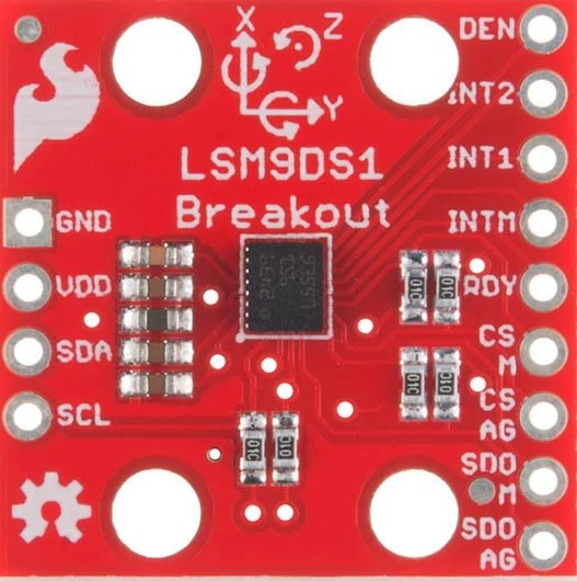
The Sparkfun 9DOF Breakout Board (SKU: SEN-13284) is a compact and versatile sensor module that integrates three essential motion-sensing components: a 3-axis accelerometer, a 3-axis gyroscope, and a 3-axis magnetometer. This combination provides a total of nine degrees of freedom (9DOF), enabling precise motion tracking, orientation sensing, and environmental awareness.
This breakout board is ideal for applications such as:
- Robotics and drone navigation
- Wearable devices and fitness trackers
- Virtual reality (VR) and augmented reality (AR) systems
- Motion capture and gesture recognition
- Scientific experiments and data logging
Explore Projects Built with Sparkfun 9DOF Breakout Board


Explore Projects Built with Sparkfun 9DOF Breakout Board
Technical Specifications
The Sparkfun 9DOF Breakout Board is built around the LSM9DS1 sensor, which combines the accelerometer, gyroscope, and magnetometer into a single package. Below are the key technical details:
General Specifications
| Parameter | Value |
|---|---|
| Supply Voltage | 2.4V to 3.6V |
| Logic Voltage | 1.8V to 3.6V |
| Communication Protocols | I2C (up to 400kHz) and SPI (up to 10MHz) |
| Operating Temperature | -40°C to +85°C |
| Dimensions | 1.0" x 0.9" (25.4mm x 22.86mm) |
Sensor Specifications
| Sensor | Range Options | Sensitivity/Resolution |
|---|---|---|
| Accelerometer | ±2g, ±4g, ±8g, ±16g | 0.061 mg/LSB (at ±2g) |
| Gyroscope | ±245°/s, ±500°/s, ±2000°/s | 8.75 mdps/LSB (at ±245°/s) |
| Magnetometer | ±4 gauss, ±8 gauss, ±12 gauss, ±16 gauss | 0.14 mgauss/LSB (at ±4 gauss) |
Pin Configuration
The breakout board has the following pin layout:
| Pin Name | Description |
|---|---|
| VIN | Power input (2.4V to 3.6V). Connect to 3.3V for most applications. |
| GND | Ground connection. |
| SDA | I2C data line. |
| SCL | I2C clock line. |
| CS_AG | Chip select for accelerometer and gyroscope (used in SPI mode). |
| CS_M | Chip select for magnetometer (used in SPI mode). |
| SDO_AG | SPI data output for accelerometer and gyroscope. |
| SDO_M | SPI data output for magnetometer. |
| INT1 | Interrupt 1 output (configurable). |
| INT2 | Interrupt 2 output (configurable). |
Usage Instructions
Connecting the 9DOF Breakout Board
- Power Supply: Connect the
VINpin to a 3.3V power source and theGNDpin to ground. - I2C Communication:
- Connect the
SDApin to the SDA pin on your microcontroller. - Connect the
SCLpin to the SCL pin on your microcontroller.
- Connect the
- SPI Communication (optional):
- Use the
CS_AG,CS_M,SDO_AG, andSDO_Mpins for SPI communication.
- Use the
- Interrupts (optional): Use the
INT1andINT2pins for interrupt-driven applications.
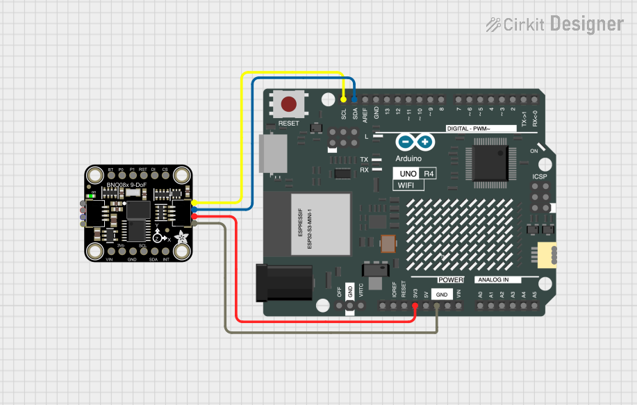
Example: Using with Arduino UNO
Below is an example of how to use the Sparkfun 9DOF Breakout Board with an Arduino UNO via I2C.
Wiring Diagram
| 9DOF Breakout Board Pin | Arduino UNO Pin |
|---|---|
| VIN | 3.3V |
| GND | GND |
| SDA | A4 |
| SCL | A5 |
Arduino Code
#include <Wire.h>
#include <SparkFunLSM9DS1.h> // Include the SparkFun LSM9DS1 library

// Create an instance of the LSM9DS1 object
LSM9DS1 imu;

// Define I2C address for the LSM9DS1
#define LSM9DS1_M  0x1E // Magnetometer I2C address
#define LSM9DS1_AG 0x6B // Accelerometer and gyroscope I2C address

void setup() {
  Serial.begin(9600); // Initialize serial communication
  Wire.begin();       // Initialize I2C communication

  // Initialize the LSM9DS1 sensor
  if (!imu.begin(LSM9DS1_AG, LSM9DS1_M)) {
    Serial.println("Failed to initialize LSM9DS1. Check connections.");
    while (1); // Halt the program if initialization fails
  }

  Serial.println("LSM9DS1 initialized successfully!");
}

void loop() {
  // Read accelerometer data
  if (imu.accelAvailable()) {
    imu.readAccel();
    Serial.print("Accel X: "); Serial.print(imu.ax);
    Serial.print(" Y: "); Serial.print(imu.ay);
    Serial.print(" Z: "); Serial.println(imu.az);
  }

  // Read gyroscope data
  if (imu.gyroAvailable()) {
    imu.readGyro();
    Serial.print("Gyro X: "); Serial.print(imu.gx);
    Serial.print(" Y: "); Serial.print(imu.gy);
    Serial.print(" Z: "); Serial.println(imu.gz);
  }

  // Read magnetometer data
  if (imu.magAvailable()) {
    imu.readMag();
    Serial.print("Mag X: "); Serial.print(imu.mx);
    Serial.print(" Y: "); Serial.print(imu.my);
    Serial.print(" Z: "); Serial.println(imu.mz);
  }

  delay(500); // Delay for readability
}
Best Practices
- Use a level shifter if interfacing with a 5V microcontroller, as the breakout board operates at 3.3V logic.
- Keep I2C lines as short as possible to avoid signal degradation.
- Use decoupling capacitors near the power supply pins to reduce noise.
Troubleshooting and FAQs
Common Issues
Sensor Not Responding:
- Ensure the
VINpin is connected to a 3.3V power source. - Verify the I2C connections (SDA and SCL) and ensure pull-up resistors are present if needed.
- Check the I2C addresses in your code (
0x1Efor magnetometer,0x6Bfor accelerometer/gyroscope).
- Ensure the
Incorrect or No Data:
- Confirm that the sensor is properly initialized in the code.
- Ensure the correct range settings are configured for each sensor.
Noise in Sensor Readings:
- Use proper grounding and shielding to minimize electrical noise.
- Apply software filtering or averaging to smooth out the data.
FAQs
Q: Can I use this board with a 5V microcontroller?
A: Yes, but you must use a logic level shifter to convert the 5V signals to 3.3V.
Q: How do I switch between I2C and SPI modes?
A: By default, the board operates in I2C mode. To use SPI, connect the CS_AG and CS_M pins to your microcontroller and configure the SPI settings in your code.
Q: What is the maximum sampling rate of the sensors?
A: The accelerometer and gyroscope can sample at up to 952 Hz, while the magnetometer can sample at up to 80 Hz.