How to Use Piezo Speaker 2test: Examples, Pinouts, and Specs

Introduction
A piezo speaker is a type of speaker that uses the piezoelectric effect to produce sound. It converts electrical energy into mechanical energy, creating sound waves through the vibration of a piezoelectric material. Piezo speakers are compact, lightweight, and energy-efficient, making them ideal for a variety of applications.
Explore Projects Built with Piezo Speaker 2test
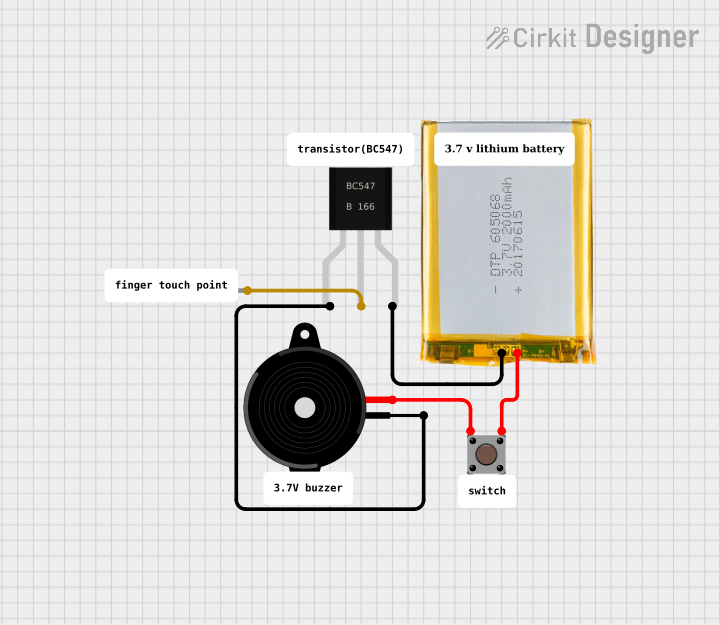
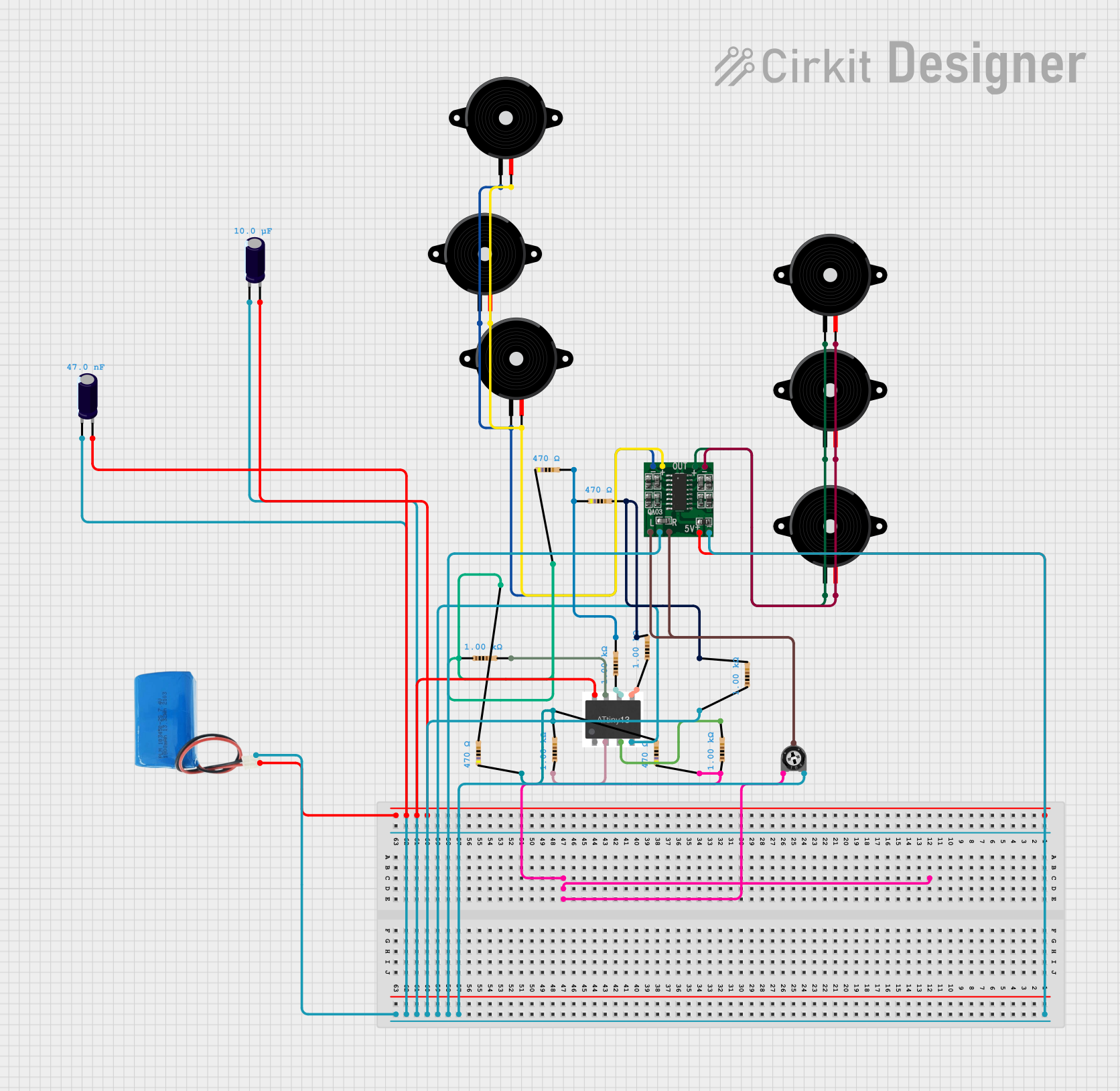
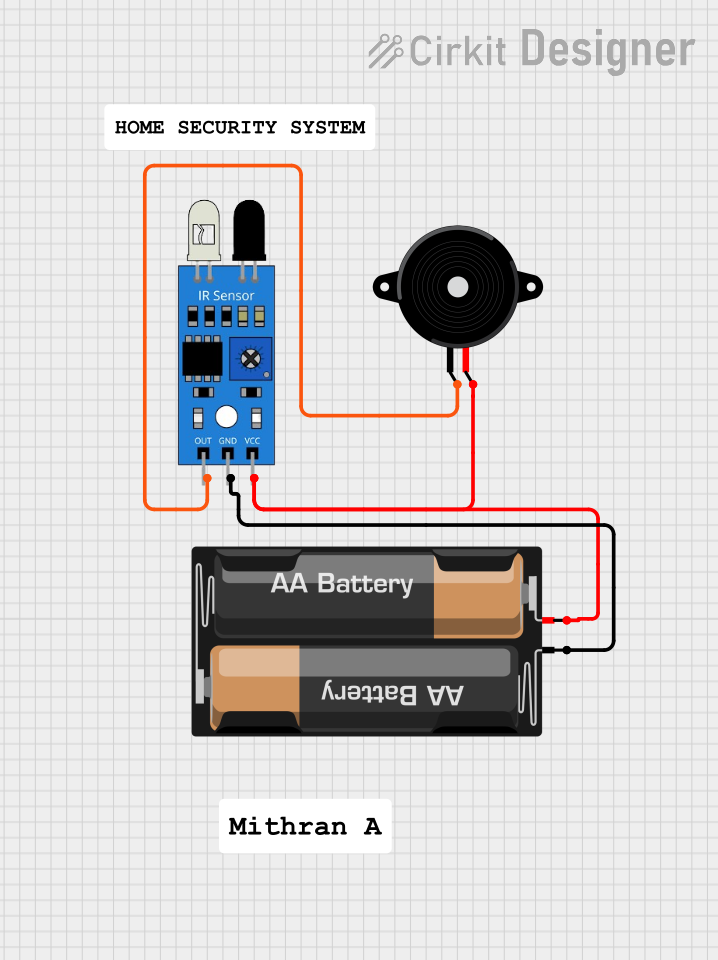
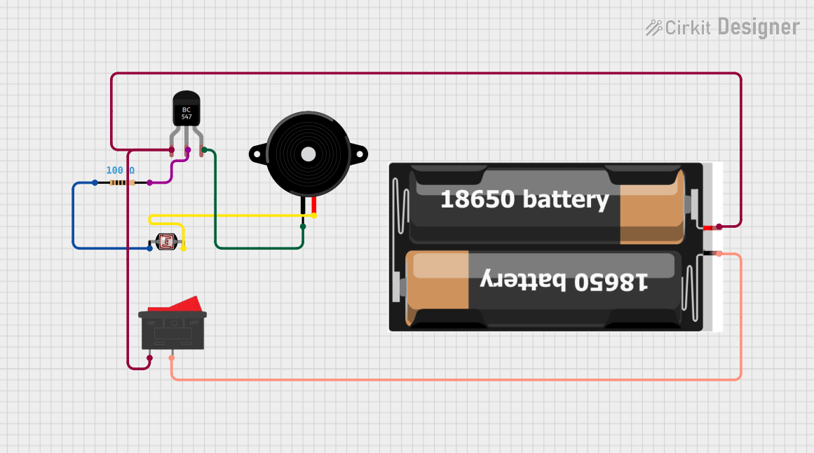
Explore Projects Built with Piezo Speaker 2test
Common Applications and Use Cases
- Alarm systems and buzzers
- Timers and notification systems
- Toys and small electronic devices
- Arduino and microcontroller projects
- Sound signaling in industrial equipment
Technical Specifications
Below are the key technical details for a typical piezo speaker:
| Parameter | Value |
|---|---|
| Operating Voltage | 3V to 12V |
| Operating Current | 5mA to 30mA |
| Resonant Frequency | 2 kHz to 4 kHz (varies by model) |
| Sound Pressure Level | 85 dB to 100 dB (at 10 cm) |
| Dimensions | Varies (e.g., 20mm diameter) |
| Operating Temperature | -20°C to +60°C |
Pin Configuration and Descriptions
Piezo speakers typically have two pins:
| Pin | Description |
|---|---|
| Positive (+) | Connects to the positive voltage supply or signal source. |
| Negative (-) | Connects to ground (GND). |
Usage Instructions
How to Use the Component in a Circuit
- Basic Connection: Connect the positive pin of the piezo speaker to the output signal (e.g., from a microcontroller or oscillator circuit). Connect the negative pin to the ground (GND).
- Driving with a Microcontroller: Use a digital output pin from a microcontroller (e.g., Arduino) to send a square wave signal to the piezo speaker. This will produce sound at the desired frequency.
- Frequency Control: The pitch of the sound is determined by the frequency of the signal applied to the piezo speaker. For example, a 2 kHz signal will produce a 2 kHz tone.
Important Considerations and Best Practices
- Voltage Limits: Ensure the applied voltage does not exceed the maximum operating voltage of the piezo speaker to avoid damage.
- Current Limiting: If necessary, use a resistor in series with the piezo speaker to limit current.
- Frequency Range: Operate the piezo speaker within its resonant frequency range for optimal sound output.
- Mounting: Secure the piezo speaker properly to avoid unwanted vibrations or noise.
Example: Using a Piezo Speaker with Arduino UNO
Below is an example code to generate a tone using a piezo speaker connected to an Arduino UNO:
// Example: Generate a tone on a piezo speaker using Arduino UNO
// Connect the positive pin of the piezo speaker to pin 8 on the Arduino
// Connect the negative pin of the piezo speaker to GND

int speakerPin = 8; // Pin connected to the piezo speaker

void setup() {
  pinMode(speakerPin, OUTPUT); // Set the speaker pin as an output
}

void loop() {
  tone(speakerPin, 1000); // Generate a 1 kHz tone
  delay(500);             // Wait for 500 milliseconds
  noTone(speakerPin);     // Stop the tone
  delay(500);             // Wait for 500 milliseconds
}
Notes:
- The
tone()function generates a square wave at the specified frequency (in Hz). - The
noTone()function stops the sound output.
Troubleshooting and FAQs
Common Issues and Solutions
No Sound Output:
- Cause: Incorrect wiring or loose connections.
- Solution: Verify that the positive and negative pins are connected correctly. Ensure the signal source is functioning.
Distorted Sound:
- Cause: Operating outside the resonant frequency range or insufficient voltage.
- Solution: Adjust the signal frequency to match the resonant frequency of the piezo speaker. Check the voltage supply.
Low Volume:
- Cause: Insufficient drive current or improper mounting.
- Solution: Ensure the current is within the recommended range. Secure the piezo speaker to a solid surface for better sound amplification.
Overheating:
- Cause: Exceeding the maximum voltage or current rating.
- Solution: Use a resistor to limit current and ensure the voltage is within the specified range.
FAQs
Q: Can I use a piezo speaker with a battery-powered circuit?
A: Yes, piezo speakers are energy-efficient and can be used in battery-powered circuits. Ensure the battery voltage matches the operating voltage of the speaker.
Q: How do I produce different tones with a piezo speaker?
A: Vary the frequency of the signal applied to the piezo speaker. For example, use the tone() function in Arduino to generate different frequencies.
Q: Can I use a piezo speaker for playing music?
A: Piezo speakers are best suited for simple tones and beeps. For high-quality music playback, consider using a dynamic speaker.
Q: What is the difference between a piezo speaker and a buzzer?
A: A piezo speaker requires an external signal to produce sound, while a buzzer typically has an internal oscillator and produces sound when powered.