How to Use Optical Encoder Sensor Module: Examples, Pinouts, and Specs
Introduction
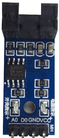
An optical encoder sensor module is an electronic device that converts the mechanical motion of a rotating or linear object into digital signals. It uses a light-emitting diode (LED) as a light source and a photodetector to sense the light interrupted by a patterned encoder wheel or disk. This sensor is commonly used in robotics, motors, and systems requiring precise motion control and feedback.
Explore Projects Built with Optical Encoder Sensor Module
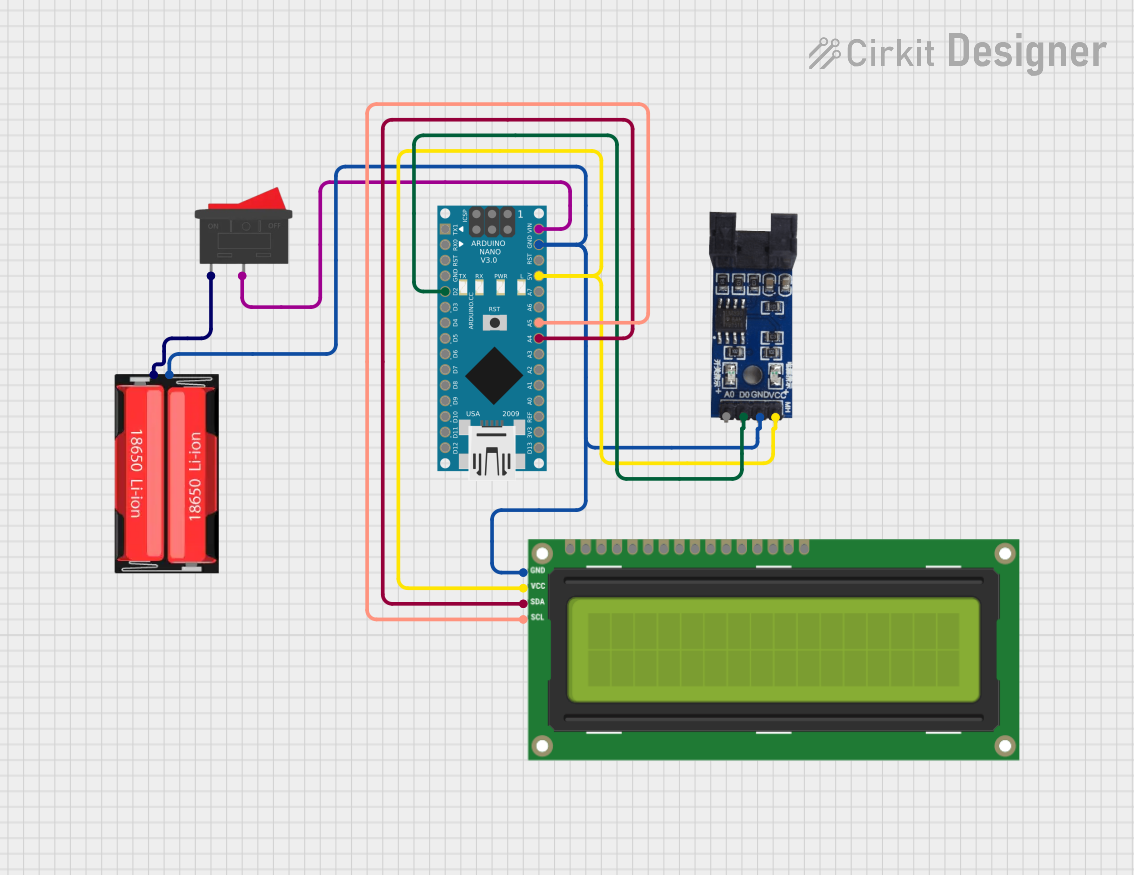

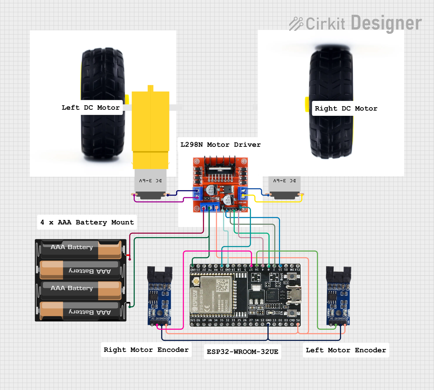
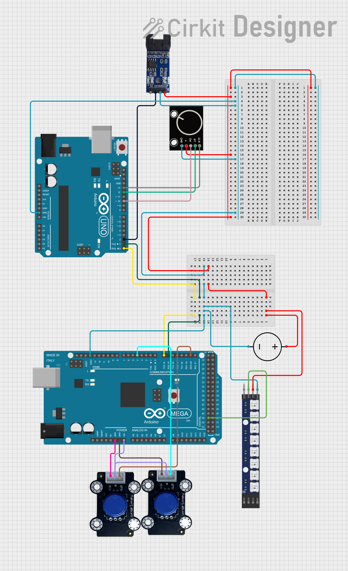
Explore Projects Built with Optical Encoder Sensor Module
Common Applications and Use Cases
- Rotary position sensing in motors
- Feedback control for servo mechanisms
- Measurement of distance or speed in conveyor systems
- User input devices like rotary knobs or mouse scroll wheels
Technical Specifications
Key Technical Details
- Operating Voltage: Typically 3.3V to 5V
- Output Signal: Digital square wave
- Pulses per Revolution: Varies by model (e.g., 100, 200, 400, 600 PPR)
- Maximum Rotational Speed: Depends on encoder specifications
- Operating Temperature Range: Usually -10°C to +70°C
Pin Configuration and Descriptions
| Pin Name | Description |
|---|---|
| VCC | Power supply (3.3V to 5V) |
| GND | Ground |
| A | Output channel A (digital signal) |
| B | Output channel B (digital signal) |
| Z | Index pulse (optional, not on all encoders) |
Usage Instructions
How to Use the Component in a Circuit
- Power Connection: Connect the VCC pin to a 3.3V or 5V power supply and the GND pin to the ground.
- Signal Connection: Connect the output channels A and B to digital input pins on a microcontroller.
- Mounting: Secure the encoder wheel or disk to the rotating part of your system.
Important Considerations and Best Practices
- Ensure that the encoder disk is properly aligned with the sensor module.
- Avoid exposing the sensor to direct sunlight or strong artificial light sources that could interfere with the readings.
- Use pull-up resistors on the output lines if the microcontroller's internal pull-ups are insufficient.
- Debounce the digital signals in software to prevent false readings due to mechanical vibrations.
Example Code for Arduino UNO
// Define the pin connections
const int encoderPinA = 2; // Channel A
const int encoderPinB = 3; // Channel B

// Variables to store encoder state
volatile int encoderPos = 0;
bool encoderALast = LOW;
bool encoderBLast = LOW;

void setup() {
  pinMode(encoderPinA, INPUT);
  pinMode(encoderPinB, INPUT);
  Serial.begin(9600); // Start serial communication at 9600 baud
}

void loop() {
  bool encoderA = digitalRead(encoderPinA);
  bool encoderB = digitalRead(encoderPinB);
  if ((encoderALast == LOW) && (encoderA == HIGH)) {
    if (encoderB == LOW) {
      encoderPos--; // Moving backward
    } else {
      encoderPos++; // Moving forward
    }
  }
  encoderALast = encoderA;
  Serial.println(encoderPos); // Print the position
}
Troubleshooting and FAQs
Common Issues Users Might Face
- Erratic Signals: This can be due to electrical noise or improper alignment of the encoder disk. Ensure that the encoder is mounted correctly and consider using shielded cables.
- No Output: Check the power supply connections and verify that the encoder wheel is not obstructing the sensor completely.
- Inconsistent Counts: Make sure that the microcontroller is reading the encoder signals correctly. Debouncing in software or hardware may be necessary.
Solutions and Tips for Troubleshooting
- If the encoder output is noisy, add a small capacitor (e.g., 0.1 µF) between the VCC and GND pins to filter out noise.
- Use a scope or logic analyzer to check the quality of the digital signals from the encoder.
- Ensure that the encoder's mounting does not introduce mechanical play, which can cause inconsistent readings.
FAQs
Q: Can I use this encoder with a 3.3V system?
A: Yes, most optical encoder sensor modules can operate at 3.3V.
Q: How do I increase the resolution of the encoder?
A: Use an encoder with more pulses per revolution (PPR) or implement software interpolation techniques.
Q: What is the purpose of the Z channel?
A: The Z channel, when present, provides an index pulse once per revolution, which can be used for precise position calibration.
Q: Can I use this encoder for linear motion?
A: Yes, but you will need a linear pattern for the encoder and a way to translate linear motion to the encoder disk or strip.