How to Use e stop: Examples, Pinouts, and Specs

Introduction
An emergency stop (e-stop) is a critical safety device designed to immediately halt machinery or equipment during an emergency. It ensures the safety of operators, prevents accidents, and minimizes potential damage to equipment. E-stops are typically large, red, and highly visible buttons or switches that are easy to activate in urgent situations. They are commonly used in industrial machinery, manufacturing systems, robotics, and other environments where rapid shutdown is essential for safety.
Explore Projects Built with e stop

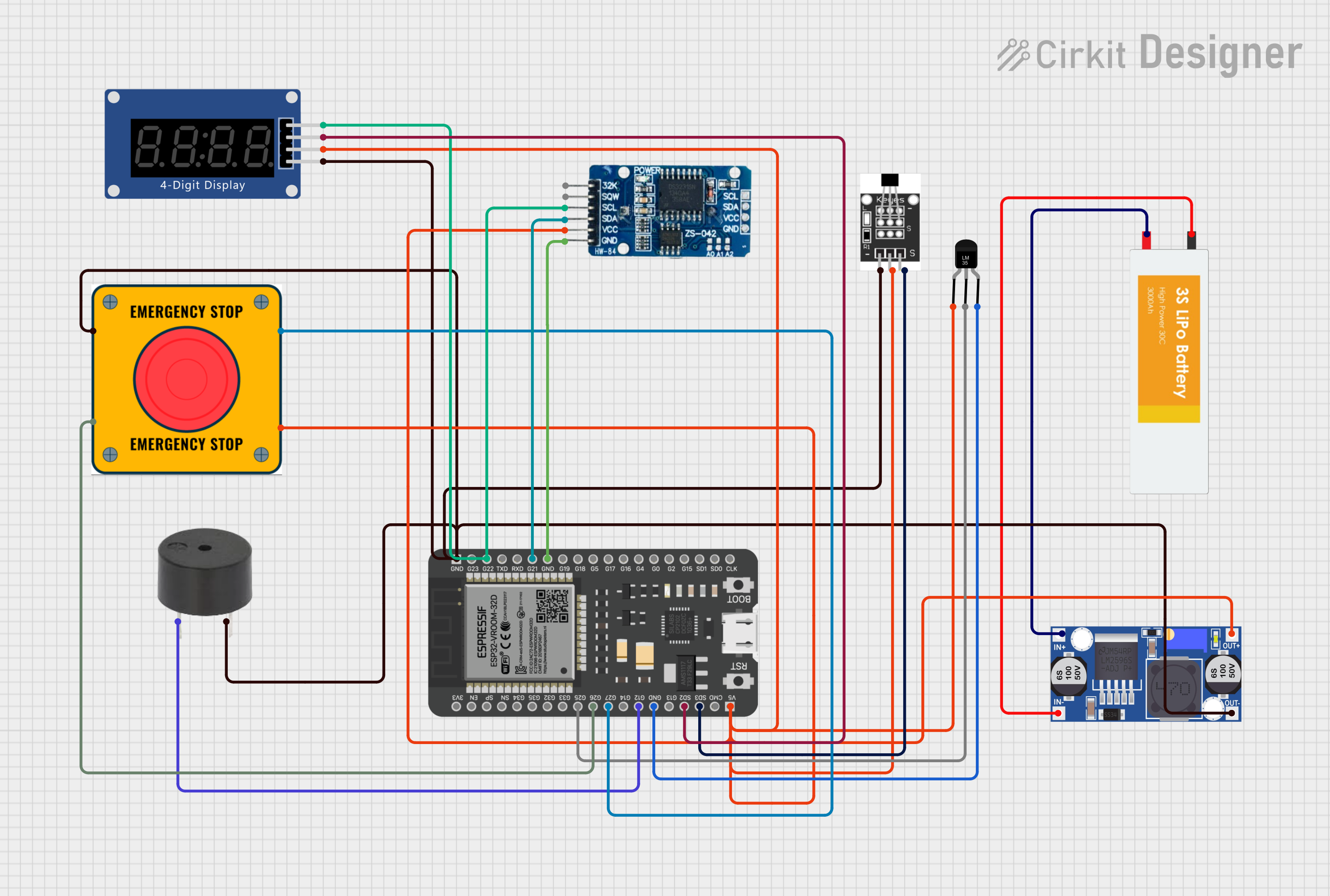


Explore Projects Built with e stop
Common Applications and Use Cases
- Industrial machinery and manufacturing equipment
- Conveyor systems and automated production lines
- Robotics and CNC machines
- Laboratory and testing equipment
- Elevators and escalators
- Any system requiring immediate shutdown for safety
Technical Specifications
Below are the general technical specifications for a standard emergency stop button. Note that specific models may vary slightly in their ratings and features.
| Parameter | Specification |
|---|---|
| Operating Voltage | 24V DC, 110V AC, or 230V AC (varies by model) |
| Current Rating | 1A to 10A (depending on application) |
| Contact Configuration | Normally Closed (NC) or Normally Open (NO) |
| Actuation Force | 22-30 N |
| Reset Mechanism | Twist-to-release or pull-to-release |
| Mounting Hole Diameter | 22mm or 30mm (standard sizes) |
| IP Rating | IP65 or higher (dust and water resistance) |
| Operating Temperature | -25°C to +70°C |
| Mechanical Durability | 50,000 to 1,000,000 cycles |
Pin Configuration and Descriptions
Emergency stop buttons typically have terminals for connecting to a circuit. Below is a table describing the pin configuration for a standard e-stop with both NC and NO contacts.
| Pin Label | Description |
|---|---|
| NC (Normally Closed) | Opens the circuit when the button is pressed, interrupting power. |
| NO (Normally Open) | Closes the circuit when the button is pressed, triggering an action. |
| COM (Common) | Common terminal shared between NC and NO contacts. |
Usage Instructions
How to Use the Component in a Circuit
- Determine the Circuit Type: Identify whether the e-stop will be used to interrupt power (NC) or trigger an alarm or signal (NO).
- Wiring the E-Stop:
- For power interruption: Connect the NC terminal in series with the power supply line to the equipment.
- For signaling: Connect the NO terminal to the input of a controller or alarm system.
- Mounting: Install the e-stop in a visible and easily accessible location. Use a 22mm or 30mm mounting hole, depending on the button size.
- Testing: After installation, test the e-stop to ensure it functions correctly. Press the button to verify that the circuit is interrupted or the signal is triggered, and reset it using the twist or pull mechanism.
Important Considerations and Best Practices
- Compliance: Ensure the e-stop complies with relevant safety standards (e.g., ISO 13850, IEC 60947-5-5).
- Accessibility: Place the e-stop in a location that is easily reachable during emergencies.
- Regular Testing: Periodically test the e-stop to confirm its functionality.
- Labeling: Clearly label the e-stop to indicate its purpose.
- Debouncing: If connecting the e-stop to a microcontroller (e.g., Arduino), implement debouncing to avoid false triggers.
Example: Connecting an E-Stop to an Arduino UNO
Below is an example of how to connect an e-stop to an Arduino UNO to monitor its state.
Circuit Description
- The NC terminal of the e-stop is connected to a digital input pin on the Arduino.
- A pull-up resistor is used to ensure the input pin reads HIGH when the e-stop is not pressed.
Code Example
// Define the pin connected to the e-stop
const int eStopPin = 2; // Digital pin 2

void setup() {
  pinMode(eStopPin, INPUT_PULLUP); // Enable internal pull-up resistor
  Serial.begin(9600); // Initialize serial communication
}

void loop() {
  int eStopState = digitalRead(eStopPin); // Read the state of the e-stop

  if (eStopState == HIGH) {
    // E-stop is not pressed
    Serial.println("System running normally.");
  } else {
    // E-stop is pressed
    Serial.println("Emergency stop activated! Shutting down...");
    // Add code here to safely shut down the system
  }

  delay(500); // Delay for stability
}
Note: The internal pull-up resistor ensures the pin reads HIGH when the e-stop is not pressed. When the e-stop is pressed, the circuit is interrupted, and the pin reads LOW.
Troubleshooting and FAQs
Common Issues and Solutions
| Issue | Solution |
|---|---|
| E-stop does not interrupt the circuit | Verify wiring connections and ensure the NC terminal is used for power interruption. |
| E-stop does not reset after activation | Check the reset mechanism (twist or pull) and ensure it is functioning properly. |
| False triggers in microcontroller setup | Implement hardware or software debouncing to filter out noise. |
| E-stop is not easily accessible | Relocate the e-stop to a more visible and reachable position. |
FAQs
Can I use an e-stop with both NC and NO contacts simultaneously? Yes, you can use both contacts simultaneously for different purposes, such as interrupting power (NC) and triggering an alarm (NO).
What is the difference between twist-to-release and pull-to-release mechanisms?
- Twist-to-release requires the user to twist the button to reset it.
- Pull-to-release requires the user to pull the button outward to reset it.
How often should I test the e-stop? It is recommended to test the e-stop at least once a month or as per your organization's safety protocols.
Can I use an e-stop in outdoor environments? Yes, but ensure the e-stop has an appropriate IP rating (e.g., IP65 or higher) for protection against dust and water.
By following this documentation, you can safely and effectively integrate an emergency stop button into your system, ensuring enhanced safety and compliance with industry standards.