How to Use mmWave Sensor: Examples, Pinouts, and Specs
Introduction
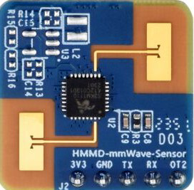
The Waveshare Human Micro-Motion Detector is a high-precision mmWave sensor designed to detect human presence, motion, and micro-movements using millimeter-wave frequencies. This sensor operates in the 24 GHz ISM band, making it suitable for a wide range of applications, including gesture recognition, security systems, smart home automation, and industrial monitoring. Its ability to function reliably in various environmental conditions, such as low light or through non-metallic barriers, makes it a versatile and robust solution for motion detection.
Explore Projects Built with mmWave Sensor
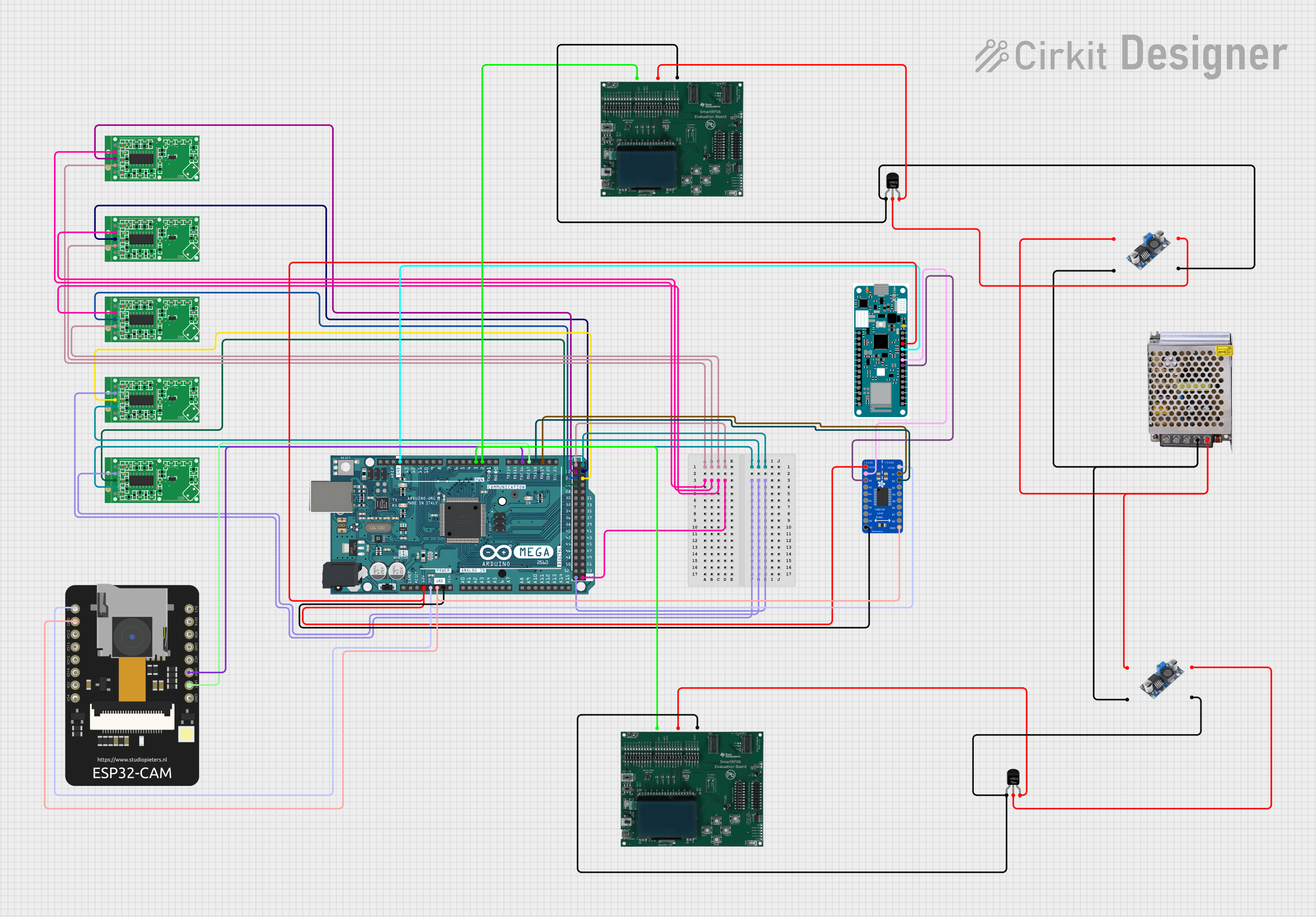
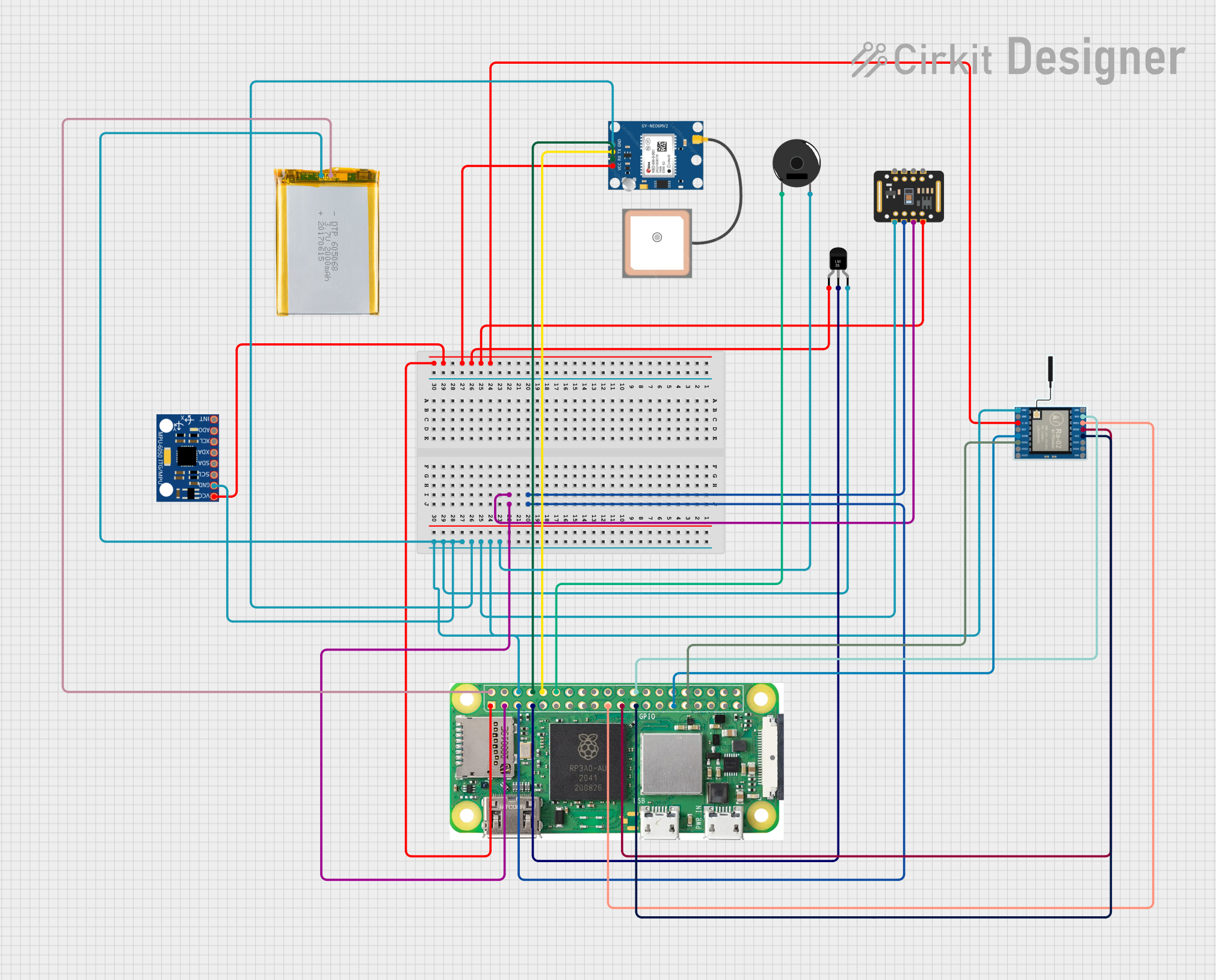

Explore Projects Built with mmWave Sensor
Common Applications
- Human presence detection in smart home systems
- Gesture recognition for touchless control interfaces
- Security and surveillance systems
- Industrial automation and monitoring
- Healthcare applications, such as monitoring patient movement
Technical Specifications
The following table outlines the key technical details of the Waveshare Human Micro-Motion Detector:
| Parameter | Value |
|---|---|
| Operating Frequency | 24 GHz ISM Band |
| Detection Range | 0.5 m to 9 m |
| Detection Angle | ±60° Horizontal, ±30° Vertical |
| Operating Voltage | 5 V DC |
| Operating Current | ≤ 60 mA |
| Communication Interface | UART (3.3V TTL) |
| Operating Temperature | -40°C to 85°C |
| Dimensions | 25 mm × 25 mm |
Pin Configuration and Descriptions
The mmWave sensor has a 4-pin interface for power and communication. The pinout is as follows:
| Pin | Name | Description |
|---|---|---|
| 1 | VCC | Power supply input (5 V DC) |
| 2 | GND | Ground connection |
| 3 | TX | UART Transmit pin (3.3V TTL) |
| 4 | RX | UART Receive pin (3.3V TTL) |
Usage Instructions
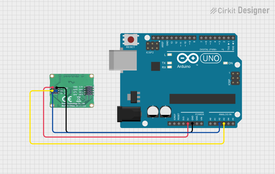
How to Use the Component in a Circuit
- Power Supply: Connect the VCC pin to a 5 V DC power source and the GND pin to the ground.
- UART Communication: Connect the TX and RX pins to the corresponding RX and TX pins of a microcontroller (e.g., Arduino UNO). Use a logic level shifter if your microcontroller operates at 5 V logic levels.
- Placement: Mount the sensor in a location with a clear line of sight to the detection area. Avoid placing it near metallic objects that may interfere with the mmWave signals.
Important Considerations and Best Practices
- Ensure the sensor is powered with a stable 5 V DC supply to avoid malfunction.
- The sensor's detection range and angle may vary depending on environmental factors such as temperature, humidity, and obstacles.
- Avoid placing the sensor near strong electromagnetic interference sources, such as motors or high-frequency devices.
- Use proper UART settings: 115200 baud rate, 8 data bits, no parity, and 1 stop bit (8N1).
Example Code for Arduino UNO
Below is an example code snippet to interface the mmWave sensor with an Arduino UNO:
// Include the SoftwareSerial library for UART communication
#include <SoftwareSerial.h>

// Define RX and TX pins for the mmWave sensor
#define RX_PIN 10  // Arduino pin connected to the sensor's TX pin
#define TX_PIN 11  // Arduino pin connected to the sensor's RX pin

// Create a SoftwareSerial object
SoftwareSerial mmWaveSerial(RX_PIN, TX_PIN);

void setup() {
  // Initialize the serial communication with the sensor
  mmWaveSerial.begin(115200); // Set baud rate to 115200
  Serial.begin(9600);         // Initialize Serial Monitor for debugging

  Serial.println("mmWave Sensor Initialized");
}

void loop() {
  // Check if data is available from the sensor
  if (mmWaveSerial.available()) {
    String sensorData = ""; // Variable to store incoming data

    // Read data from the sensor
    while (mmWaveSerial.available()) {
      char c = mmWaveSerial.read();
      sensorData += c;
    }

    // Print the received data to the Serial Monitor
    Serial.println("Sensor Data: " + sensorData);
  }

  delay(100); // Add a small delay to avoid overwhelming the sensor
}
Notes:
- Ensure the RX and TX pins are correctly connected to avoid communication errors.
- Use the Serial Monitor in the Arduino IDE to view the sensor's output.
Troubleshooting and FAQs
Common Issues and Solutions
No Data Received from the Sensor
- Cause: Incorrect UART connection or baud rate mismatch.
- Solution: Verify the TX and RX connections and ensure the baud rate is set to 115200.
Inconsistent Detection Results
- Cause: Environmental interference or improper sensor placement.
- Solution: Ensure the sensor is placed in a clear area, away from metallic objects or strong electromagnetic sources.
Sensor Not Powering On
- Cause: Insufficient power supply or loose connections.
- Solution: Check the power supply voltage and ensure all connections are secure.
FAQs
Can the sensor detect through walls or glass?
- The sensor can detect through non-metallic barriers, such as glass or plastic, but detection range and accuracy may be reduced.
What is the maximum detection range?
- The sensor can detect objects up to 9 meters away under optimal conditions.
Is the sensor compatible with 5 V logic microcontrollers?
- The sensor operates at 3.3 V logic levels. Use a logic level shifter when interfacing with 5 V logic microcontrollers.
Can the sensor detect stationary objects?
- The sensor is optimized for detecting motion and micro-movements. It may not reliably detect completely stationary objects.
By following this documentation, users can effectively integrate the Waveshare Human Micro-Motion Detector into their projects and troubleshoot common issues.