How to Use 5V 5A Dual PD Power Module: Examples, Pinouts, and Specs
Introduction
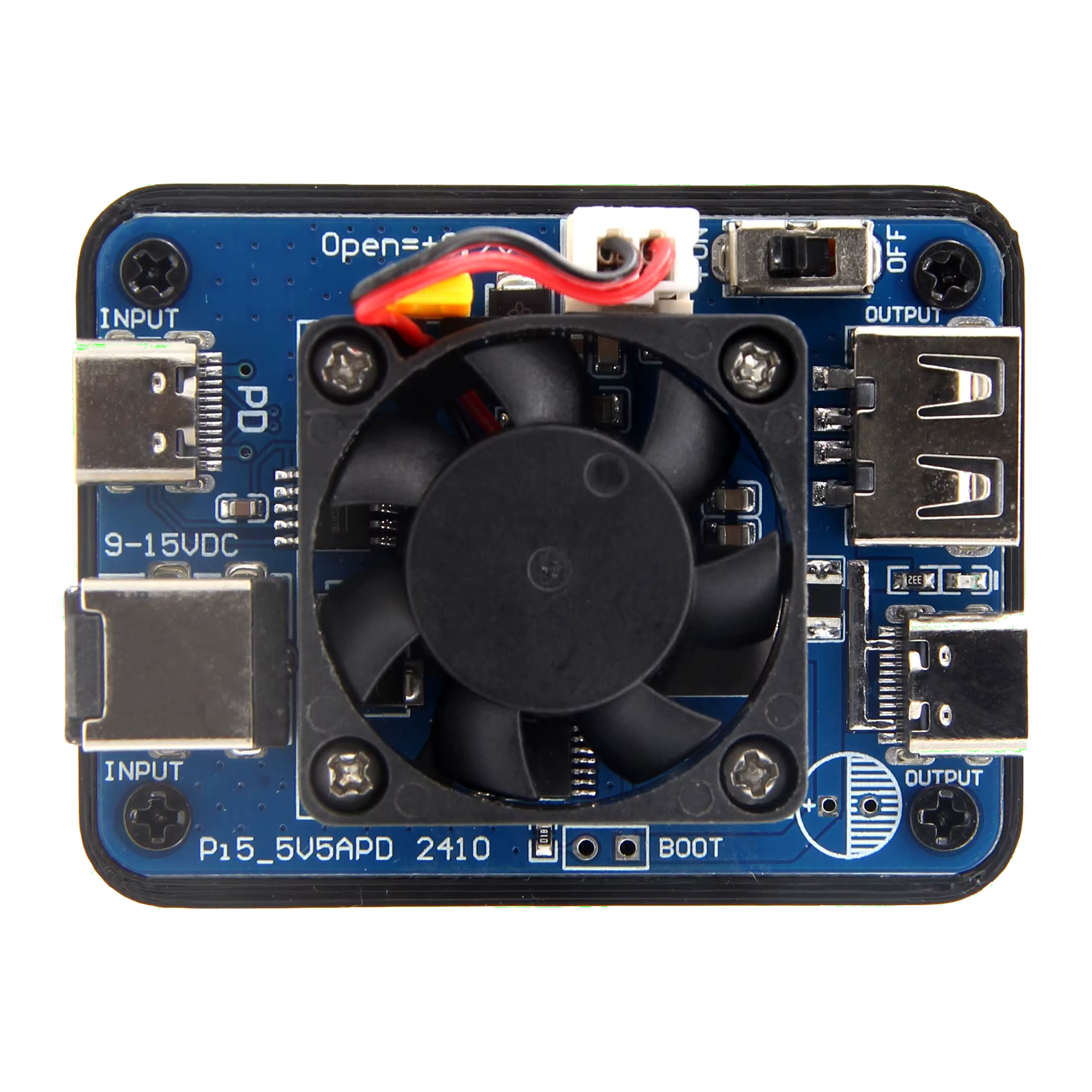
The 5V 5A Dual PD Power Module by Geekworm is a versatile power delivery module designed to provide dual USB Power Delivery (PD) outputs. It is capable of delivering up to 5 volts and 5 amps of current per output, making it ideal for powering a wide range of electronic devices and projects. This module is particularly useful for charging USB-powered devices, powering single-board computers like the Raspberry Pi, or supplying power to DIY electronics projects.
Explore Projects Built with 5V 5A Dual PD Power Module


Explore Projects Built with 5V 5A Dual PD Power Module
Common Applications and Use Cases
- Charging smartphones, tablets, and other USB-powered devices.
- Powering single-board computers (e.g., Raspberry Pi, Arduino).
- Supplying power to robotics and IoT projects.
- Providing a stable power source for prototyping and testing circuits.
Technical Specifications
Below are the key technical details of the 5V 5A Dual PD Power Module:
| Parameter | Specification |
|---|---|
| Input Voltage | 6V to 36V DC |
| Output Voltage | 5V DC (fixed) |
| Output Current | Up to 5A per port |
| Number of Outputs | 2 USB Type-C PD ports |
| Efficiency | Up to 95% |
| Protection Features | Overcurrent, overvoltage, short-circuit |
| Operating Temperature | -40°C to 85°C |
| Dimensions | 50mm x 30mm x 12mm |
Pin Configuration and Descriptions
The module has the following input and output connections:
Input Pins
| Pin Name | Description |
|---|---|
| VIN+ | Positive DC input voltage (6V to 36V) |
| VIN- | Negative DC input (ground) |
Output Ports
| Port Name | Description |
|---|---|
| USB-C PD1 | USB Type-C Power Delivery output (5V, 5A max) |
| USB-C PD2 | USB Type-C Power Delivery output (5V, 5A max) |
Usage Instructions
How to Use the Module in a Circuit
Connect the Input Voltage:
- Connect a DC power source (6V to 36V) to the
VIN+andVIN-pins. Ensure the power source can supply sufficient current for your application. - Double-check the polarity of the input connections to avoid damage.
- Connect a DC power source (6V to 36V) to the
Connect the Output Devices:
- Plug your USB-powered devices into the USB-C PD1 and PD2 ports. Each port can deliver up to 5V and 5A.
Power On:
- Turn on the DC power source. The module will automatically regulate the input voltage to provide a stable 5V output.
Monitor Operation:
- Ensure the connected devices do not exceed the maximum current rating (5A per port). The module includes built-in protection features to prevent damage.
Important Considerations and Best Practices
- Input Voltage Range: Always ensure the input voltage is within the specified range (6V to 36V). Exceeding this range may damage the module.
- Heat Dissipation: At high currents, the module may generate heat. Ensure adequate ventilation or use a heatsink if necessary.
- Load Distribution: If using both USB-C ports simultaneously, ensure the total current draw does not exceed the input power supply's capacity.
- Secure Connections: Use reliable connectors and cables to prevent voltage drops or intermittent connections.
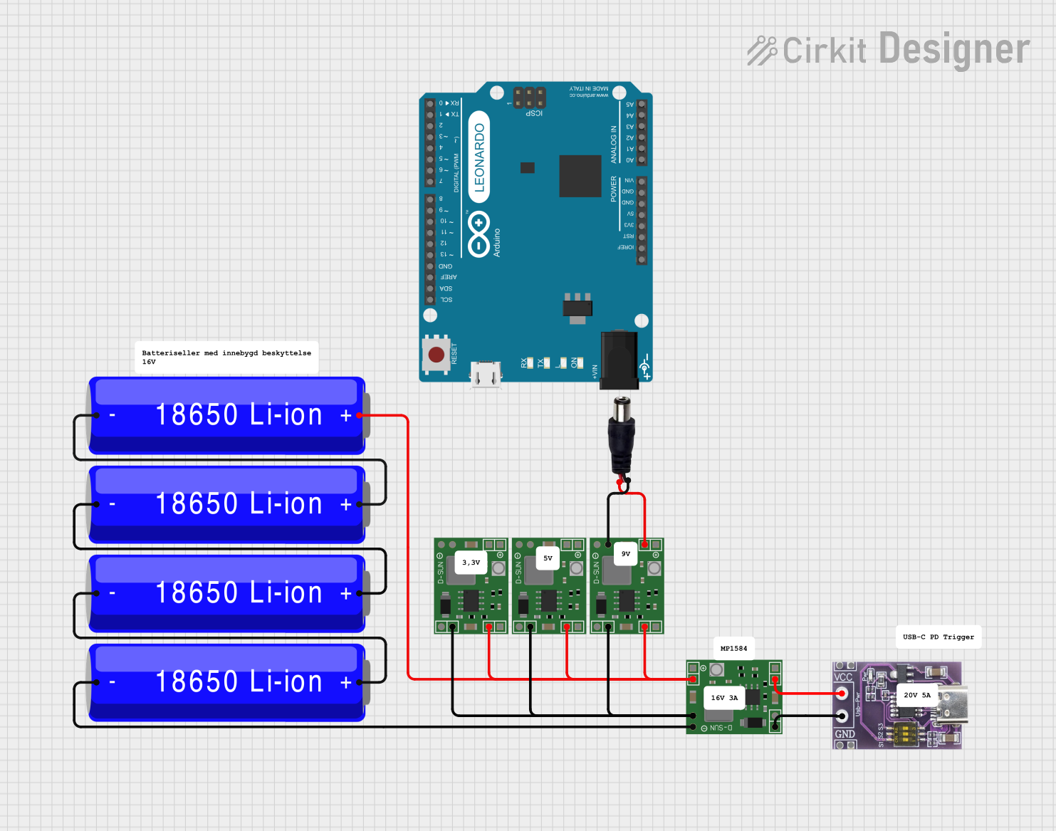
Example: Using with an Arduino UNO
The 5V 5A Dual PD Power Module can be used to power an Arduino UNO via its USB port. Below is an example of how to connect and use the module:
- Connect a 12V DC power supply to the
VIN+andVIN-pins of the module. - Plug the USB-C PD1 port into the Arduino UNO's USB port using a USB-C to USB-A cable.
- The Arduino UNO will receive a stable 5V power supply from the module.
Here is an example Arduino sketch to blink an LED while powered by the module:
// Blink an LED connected to pin 13 of the Arduino UNO
// This sketch demonstrates basic functionality while powered by the module.

void setup() {
  pinMode(13, OUTPUT); // Set pin 13 as an output
}

void loop() {
  digitalWrite(13, HIGH); // Turn the LED on
  delay(1000);            // Wait for 1 second
  digitalWrite(13, LOW);  // Turn the LED off
  delay(1000);            // Wait for 1 second
}
Troubleshooting and FAQs
Common Issues and Solutions
Module Not Powering On:
- Cause: Incorrect input voltage or polarity.
- Solution: Verify the input voltage is within the 6V to 36V range and check the polarity of the connections.
Output Voltage is Not 5V:
- Cause: Overloaded output or insufficient input power.
- Solution: Ensure the connected devices do not exceed 5A per port and verify the input power supply can handle the load.
Module Overheating:
- Cause: High current draw or poor ventilation.
- Solution: Reduce the load or improve heat dissipation with a heatsink or fan.
Connected Device Not Charging:
- Cause: Incompatible cable or device.
- Solution: Use a high-quality USB-C cable and ensure the device supports 5V input.
FAQs
Q: Can I use this module to power a Raspberry Pi?
A: Yes, the module is suitable for powering a Raspberry Pi. Use a USB-C to USB-C cable for models like the Raspberry Pi 4, or a USB-C to Micro-USB cable for older models.
Q: Is the module safe to use with sensitive electronics?
A: Yes, the module includes overcurrent, overvoltage, and short-circuit protection to ensure safe operation.
Q: Can I use both USB-C ports simultaneously?
A: Yes, both ports can be used at the same time, but ensure the total current draw does not exceed the input power supply's capacity.
Q: What happens if the input voltage exceeds 36V?
A: Exceeding the maximum input voltage may damage the module. Always use a regulated power supply within the specified range.