Cirkit Designer
Your all-in-one circuit design IDE
Home /
Component Documentation
How to Use MDV 2x2A DC Motor Controller (L298N): Examples, Pinouts, and Specs
Introduction
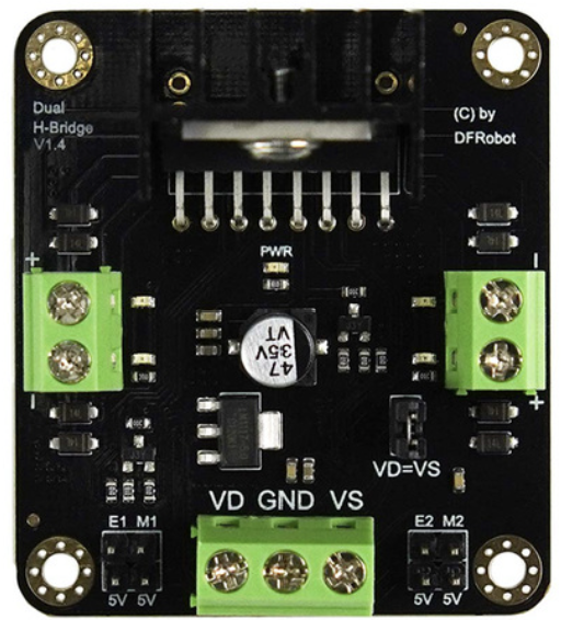
The MDV 2x2A DC Motor Controller, also known as the L298N motor driver, is a dual H-bridge motor driver module manufactured by DFRobot (Part ID: DRI0002). This versatile module allows for the control of two DC motors or one stepper motor, providing up to 2A current per channel. It is widely used in robotics, automation, and various DIY electronics projects due to its reliability and ease of use.
Explore Projects Built with MDV 2x2A DC Motor Controller (L298N)
Microcontroller-Driven Motor Control System with LCD Interface and Thermal Management
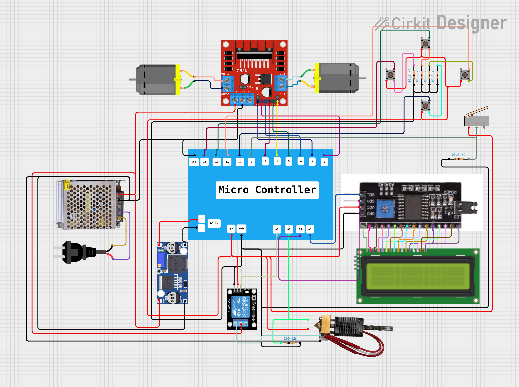
This circuit controls two DC motors using an L298N motor driver, which is interfaced with a microcontroller. The microcontroller can adjust the speed and direction of the motors, and it also manages a hot end device through a relay module. Additionally, the circuit includes an I2C module connected to an LCD screen for display purposes, multiple pushbuttons for user input, and a buck converter to regulate voltage for the microcontroller.
Battery-Powered Line Following Robot with L298N Motor Driver and KY-033 Sensors

This circuit is designed to control a two-wheeled robot using an L298N motor driver, powered by two 18650 Li-ion batteries. It includes two KY-033 line tracking sensors for navigation and a 74HC04 inverter to process sensor signals and control the motor driver inputs.
Wi-Fi Controlled Quad DC Motor Driver System
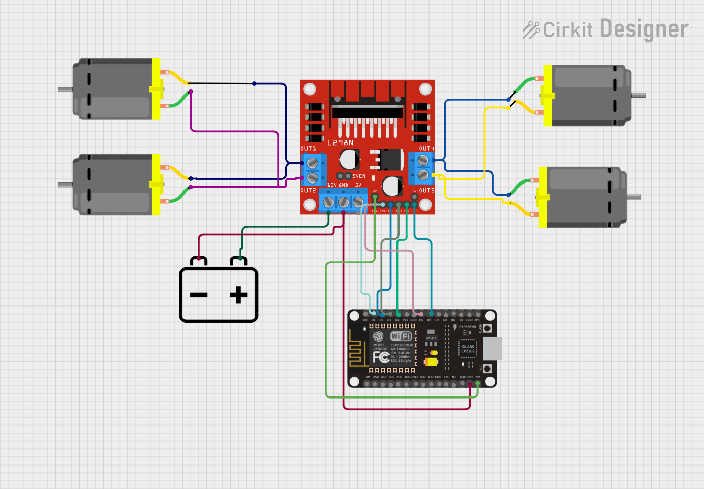
This circuit is designed to control four DC motors using an L298N motor driver module, which is interfaced with an ESP8266 NodeMCU microcontroller. The NodeMCU's digital pins (D1-D6) are connected to the input pins of the L298N to control the speed and direction of the motors. A 12V battery provides power to the motors through the motor driver, and also powers the NodeMCU through a voltage regulator on the L298N.
Battery-Powered Dual DC Motor Control with Arduino and L298N Driver
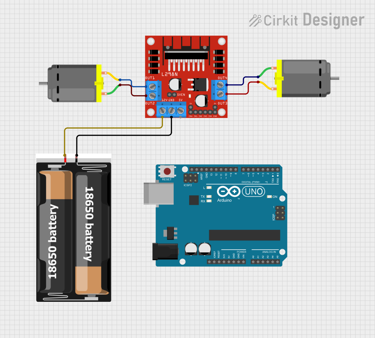
This circuit controls two DC motors using an L298N motor driver, powered by a 2x 18650 battery pack. The Arduino UNO is included but currently has no functional code, suggesting it may be intended for future control or monitoring purposes.
Explore Projects Built with MDV 2x2A DC Motor Controller (L298N)
Microcontroller-Driven Motor Control System with LCD Interface and Thermal Management
This circuit controls two DC motors using an L298N motor driver, which is interfaced with a microcontroller. The microcontroller can adjust the speed and direction of the motors, and it also manages a hot end device through a relay module. Additionally, the circuit includes an I2C module connected to an LCD screen for display purposes, multiple pushbuttons for user input, and a buck converter to regulate voltage for the microcontroller.
Battery-Powered Line Following Robot with L298N Motor Driver and KY-033 Sensors
This circuit is designed to control a two-wheeled robot using an L298N motor driver, powered by two 18650 Li-ion batteries. It includes two KY-033 line tracking sensors for navigation and a 74HC04 inverter to process sensor signals and control the motor driver inputs.
Wi-Fi Controlled Quad DC Motor Driver System
This circuit is designed to control four DC motors using an L298N motor driver module, which is interfaced with an ESP8266 NodeMCU microcontroller. The NodeMCU's digital pins (D1-D6) are connected to the input pins of the L298N to control the speed and direction of the motors. A 12V battery provides power to the motors through the motor driver, and also powers the NodeMCU through a voltage regulator on the L298N.
Battery-Powered Dual DC Motor Control with Arduino and L298N Driver
This circuit controls two DC motors using an L298N motor driver, powered by a 2x 18650 battery pack. The Arduino UNO is included but currently has no functional code, suggesting it may be intended for future control or monitoring purposes.
Common Applications and Use Cases
- Robotics: Controlling the movement of robot wheels or arms.
- Automation: Driving conveyor belts or other mechanical systems.
- DIY Projects: Building remote-controlled cars, robotic arms, or other motorized devices.
- Educational Projects: Teaching motor control and electronics concepts.
Technical Specifications
Key Technical Details
| Parameter | Value |
|---|---|
| Operating Voltage | 5V to 35V |
| Output Current | 2A per channel (max) |
| Peak Output Current | 3A per channel (short duration) |
| Control Logic Voltage | 5V |
| Power Dissipation | 25W |
| Dimensions | 43mm x 43mm x 27mm |
| Weight | 26g |
Pin Configuration and Descriptions
| Pin Name | Description |
|---|---|
| IN1 | Input 1 for Motor A control |
| IN2 | Input 2 for Motor A control |
| IN3 | Input 1 for Motor B control |
| IN4 | Input 2 for Motor B control |
| ENA | Enable pin for Motor A (PWM control) |
| ENB | Enable pin for Motor B (PWM control) |
| OUT1 | Output 1 for Motor A |
| OUT2 | Output 2 for Motor A |
| OUT3 | Output 1 for Motor B |
| OUT4 | Output 2 for Motor B |
| 12V | Power supply for motors (12V to 35V) |
| 5V | 5V logic supply (can be used to power the module if no external 5V is available) |
| GND | Ground |
Usage Instructions
How to Use the Component in a Circuit
Power Connections:
- Connect the 12V pin to the positive terminal of your power supply (12V to 35V).
- Connect the GND pin to the ground terminal of your power supply.
- If you are using an external 5V supply, connect it to the 5V pin. Otherwise, the module can generate 5V from the 12V supply.
Motor Connections:
- Connect the motor terminals to OUT1 and OUT2 for Motor A.
- Connect the motor terminals to OUT3 and OUT4 for Motor B.
Control Connections:
- Connect IN1, IN2, IN3, and IN4 to the digital output pins of your microcontroller (e.g., Arduino).
- Connect ENA and ENB to PWM-capable pins of your microcontroller for speed control.
Important Considerations and Best Practices
- Heat Dissipation: The L298N can get hot during operation. Ensure adequate ventilation or use a heat sink if necessary.
- Current Limiting: Do not exceed the maximum current rating of 2A per channel to avoid damaging the module.
- Power Supply: Ensure your power supply can provide sufficient current for both the motors and the module.
Example Code for Arduino UNO
// Example code to control two DC motors using the L298N motor driver
// Connect IN1, IN2, IN3, IN4, ENA, and ENB to Arduino pins as defined below

#define IN1 7
#define IN2 6
#define IN3 5
#define IN4 4
#define ENA 9
#define ENB 10

void setup() {
  // Set all the motor control pins to outputs
  pinMode(IN1, OUTPUT);
  pinMode(IN2, OUTPUT);
  pinMode(IN3, OUTPUT);
  pinMode(IN4, OUTPUT);
  pinMode(ENA, OUTPUT);
  pinMode(ENB, OUTPUT);
}

void loop() {
  // Example: Move Motor A forward
  digitalWrite(IN1, HIGH);
  digitalWrite(IN2, LOW);
  analogWrite(ENA, 255); // Full speed

  // Example: Move Motor B backward
  digitalWrite(IN3, LOW);
  digitalWrite(IN4, HIGH);
  analogWrite(ENB, 255); // Full speed

  delay(2000); // Run for 2 seconds

  // Stop both motors
  analogWrite(ENA, 0);
  analogWrite(ENB, 0);

  delay(2000); // Wait for 2 seconds
}
Troubleshooting and FAQs
Common Issues Users Might Face
Motor Not Running:
- Solution: Check all power and ground connections. Ensure the motor is connected correctly and the control pins are set properly in the code.
Overheating:
- Solution: Ensure the module is not exceeding the current rating. Use a heat sink or improve ventilation.
Inconsistent Motor Speed:
- Solution: Verify the PWM signal is stable and correctly configured. Check the power supply for sufficient current.
Solutions and Tips for Troubleshooting
- Check Connections: Ensure all connections are secure and correctly placed.
- Verify Code: Double-check the code for any logical errors or incorrect pin assignments.
- Use Multimeter: Measure voltage and current at various points to diagnose issues.
- Consult Datasheet: Refer to the L298N datasheet for detailed technical information and troubleshooting tips.
By following this documentation, users should be able to effectively utilize the MDV 2x2A DC Motor Controller (L298N) in their projects, ensuring reliable and efficient motor control.