
How to Use ATX24 Pin Power Supply Connector: Examples, Pinouts, and Specs
 Design with ATX24 Pin Power Supply Connector in Cirkit Designer
Introduction
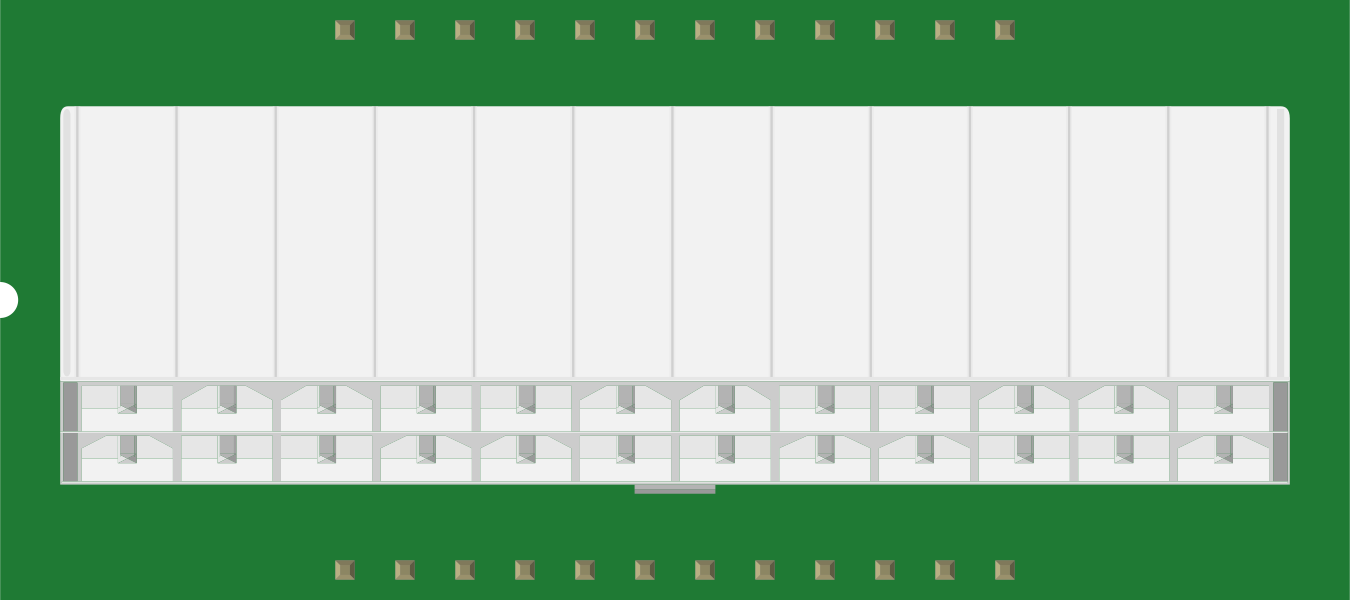
The ATX24 Pin Power Supply Connector (Manufacturer: SparkFun, Part ID: PRT-09498) is a standard connector used to deliver power from a computer's power supply unit (PSU) to the motherboard. This connector features 24 pins, providing multiple voltage levels and ground connections to support the operation of modern desktop computers. It is an essential component in ATX-compliant systems, ensuring reliable power distribution.
Explore Projects Built with ATX24 Pin Power Supply Connector
 Open Project in Cirkit Designer
 Open Project in Cirkit Designer
 Open Project in Cirkit Designer
 Open Project in Cirkit Designer
Explore Projects Built with ATX24 Pin Power Supply Connector
Open Project in Cirkit DesignerOpen Project in Cirkit DesignerOpen Project in Cirkit DesignerOpen Project in Cirkit DesignerCommon Applications and Use Cases
- Powering desktop computer motherboards in ATX systems.
- Custom PC builds and repairs.
- Prototyping and testing power delivery systems.
- Educational projects involving power supply design and analysis.
Technical Specifications
The ATX24 Pin Power Supply Connector is designed to meet the ATX standard for power delivery. Below are the key technical details:
Key Specifications
- Voltage Levels: +3.3V, +5V, +12V, -12V, and +5V Standby (SB).
- Maximum Current: Varies by voltage rail (e.g., +12V rail can handle up to 20A or more, depending on the PSU).
- Connector Type: 24-pin Molex Mini-Fit Jr.
- Pin Pitch: 4.2mm.
- Operating Temperature: -40°C to +105°C.
- Durability: Rated for 30 mating cycles.
Pin Configuration and Descriptions
The ATX24 Pin Power Supply Connector has the following pinout:
| Pin Number | Signal Name | Description | Voltage |
|---|---|---|---|
| 1 | +3.3V | Positive 3.3V power rail | +3.3V |
| 2 | +3.3V | Positive 3.3V power rail | +3.3V |
| 3 | Ground | Ground connection | 0V |
| 4 | +5V | Positive 5V power rail | +5V |
| 5 | Ground | Ground connection | 0V |
| 6 | +5V | Positive 5V power rail | +5V |
| 7 | Ground | Ground connection | 0V |
| 8 | Power Good | PSU status signal | +5V logic |
| 9 | +5V Standby | Standby power for low-power mode | +5V |
| 10 | +12V | Positive 12V power rail | +12V |
| 11 | +12V | Positive 12V power rail | +12V |
| 12 | +3.3V | Positive 3.3V power rail | +3.3V |
| 13 | +3.3V | Positive 3.3V power rail | +3.3V |
| 14 | -12V | Negative 12V power rail | -12V |
| 15 | Ground | Ground connection | 0V |
| 16 | PS_ON | Power supply on/off control | Active Low |
| 17 | Ground | Ground connection | 0V |
| 18 | Ground | Ground connection | 0V |
| 19 | Ground | Ground connection | 0V |
| 20 | No Connection | Reserved | N/A |
| 21 | +5V | Positive 5V power rail | +5V |
| 22 | +5V | Positive 5V power rail | +5V |
| 23 | +5V | Positive 5V power rail | +5V |
| 24 | Ground | Ground connection | 0V |
Usage Instructions
How to Use the Component in a Circuit
Connecting to a PSU:
- Ensure the PSU is powered off and unplugged before connecting the ATX24 Pin Power Supply Connector to the motherboard or any other circuit.
- Align the connector with the motherboard's 24-pin header and gently press it in until it clicks into place.
Testing Power Rails:
- Use a multimeter to verify the voltage levels on each pin before connecting the PSU to sensitive components.
- To power on the PSU without a motherboard, short the PS_ON pin (Pin 16) to Ground (Pin 15, 17, 18, or 19).
Prototyping:
- For custom circuits, use a breakout board or adapter to access individual pins safely.
- Ensure proper load balancing across the power rails to avoid overloading any single rail.
Important Considerations and Best Practices
- Load Requirements: Ensure the connected devices do not exceed the PSU's rated current for each voltage rail.
- Cable Management: Use cable ties or sleeves to organize wires and prevent accidental disconnections.
- Safety: Always disconnect the PSU from the mains power before working with the connector.
- Pinout Verification: Double-check the pinout to avoid incorrect connections that could damage components.
Example: Using with an Arduino UNO
The ATX24 Pin Power Supply Connector can be used to power an Arduino UNO via the +5V rail. Below is an example of how to use it:
- Connect the +5V pin (Pin 4 or 6) to the Arduino's 5V pin.
- Connect any Ground pin (e.g., Pin 3 or 5) to the Arduino's GND pin.
// Example Arduino code to blink an LED using power from the ATX24 connector
// Ensure the ATX PSU is properly powered on and providing +5V to the Arduino.

const int ledPin = 13; // Built-in LED pin on Arduino UNO

void setup() {
  pinMode(ledPin, OUTPUT); // Set LED pin as output
}

void loop() {
  digitalWrite(ledPin, HIGH); // Turn the LED on
  delay(1000);               // Wait for 1 second
  digitalWrite(ledPin, LOW);  // Turn the LED off
  delay(1000);               // Wait for 1 second
}
Troubleshooting and FAQs
Common Issues Users Might Face
PSU Does Not Power On:
- Ensure the PS_ON pin (Pin 16) is properly shorted to Ground.
- Verify that the PSU is connected to mains power and switched on.
Incorrect Voltage Levels:
- Check the PSU's specifications and ensure it is functioning correctly.
- Use a multimeter to verify the output voltages on the connector.
Overheating or Shutdown:
- Ensure the connected devices do not exceed the PSU's rated current for any voltage rail.
- Check for proper ventilation around the PSU.
Loose Connection:
- Verify that the connector is fully seated in the motherboard or breakout board.
Solutions and Tips for Troubleshooting
- Use a PSU tester to quickly diagnose issues with the ATX24 Pin Power Supply Connector.
- If the PSU fails to start, inspect the Power Good signal (Pin 8) to ensure it is at the correct logic level.
- For custom circuits, use a breakout board to safely access individual pins without risking damage to the connector.
By following this documentation, users can effectively utilize the SparkFun ATX24 Pin Power Supply Connector (PRT-09498) in their projects and troubleshoot common issues with ease.