How to Use Actuonix L16-P Linear Actuator (right facing): Examples, Pinouts, and Specs
Introduction
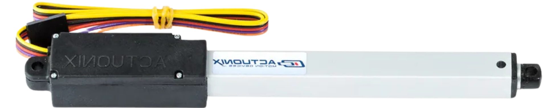
The Actuonix L16-P Linear Actuator (Model: L16-100-63-12-P) is a compact and versatile device designed to convert rotary motion into precise linear motion. This actuator is ideal for applications requiring accurate positioning and control, such as robotics, industrial automation, home automation, and prototyping. Its right-facing orientation provides additional flexibility for installation in tight or constrained spaces.
The L16-P model features an integrated potentiometer for position feedback, making it suitable for closed-loop control systems. With its compact size and robust design, this actuator is a reliable choice for projects requiring smooth and repeatable linear motion.
Explore Projects Built with Actuonix L16-P Linear Actuator (right facing)
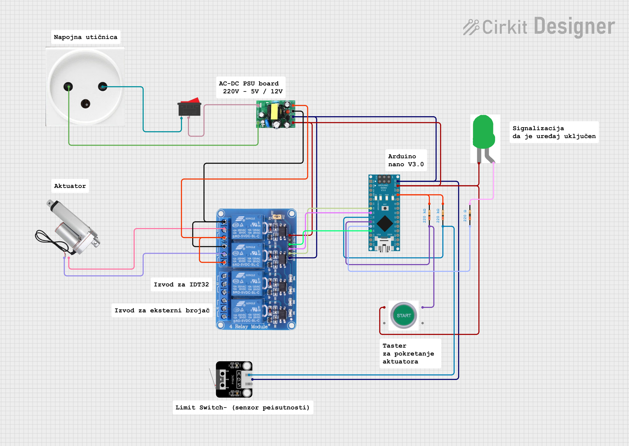

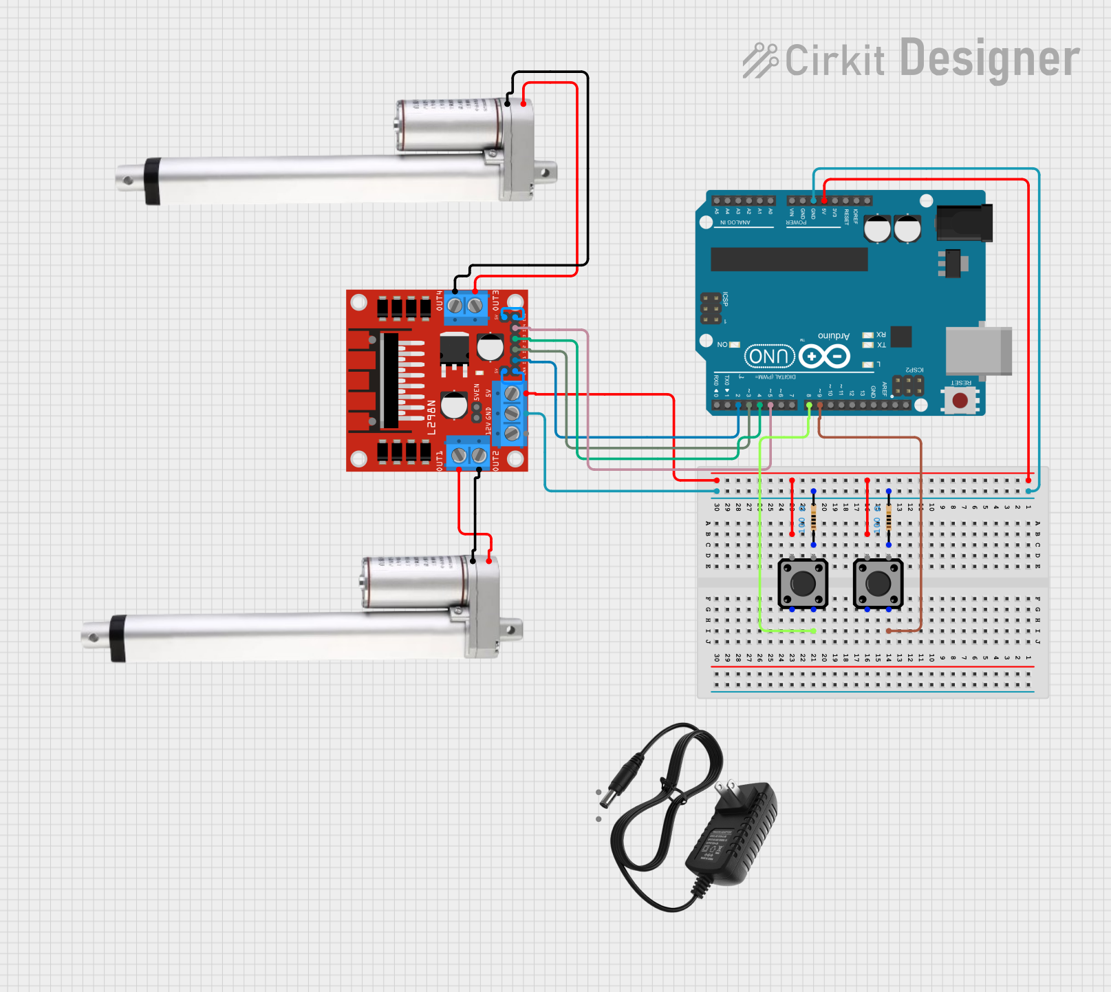
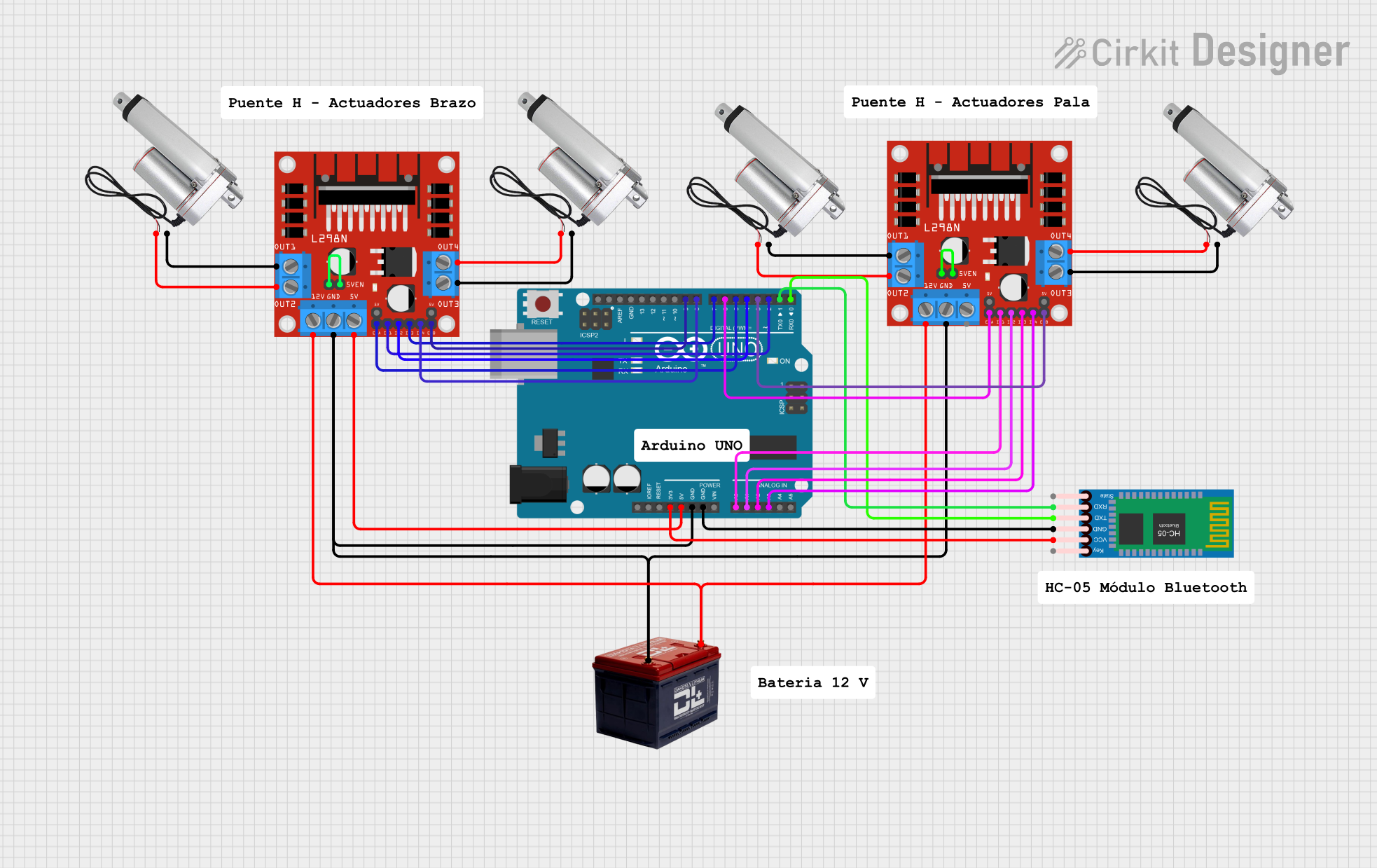
Explore Projects Built with Actuonix L16-P Linear Actuator (right facing)
Technical Specifications
Below are the key technical details of the Actuonix L16-P Linear Actuator:
| Parameter | Value |
|---|---|
| Manufacturer | Actuonix |
| Model Number | L16-100-63-12-P |
| Stroke Length | 100 mm |
| Gear Ratio | 63:1 |
| Input Voltage | 12 V DC |
| Maximum Force | 50 N |
| Maximum Speed (No Load) | 6 mm/s |
| Feedback Type | Potentiometer |
| Potentiometer Resistance | 10 kΩ |
| Potentiometer Travel | 0–10 kΩ over full stroke |
| Current Draw (No Load) | 450 mA |
| Current Draw (Stall) | 900 mA |
| Operating Temperature | -10°C to +50°C |
| Housing Material | Anodized Aluminum |
| Weight | 56 g |
Pin Configuration
The L16-P Linear Actuator has a 3-wire interface for power, ground, and feedback. The pinout is as follows:
| Wire Color | Function | Description |
|---|---|---|
| Red | Power (V+) | Connect to a 12 V DC power source. |
| Black | Ground (GND) | Connect to the ground of the power source. |
| Blue | Feedback (POT) | Provides position feedback as a voltage signal. |
Usage Instructions
How to Use the Actuator in a Circuit
Power Connection:
- Connect the red wire to the positive terminal of a 12 V DC power supply.
- Connect the black wire to the ground terminal of the power supply.
Feedback Connection:
- The blue wire outputs a voltage proportional to the actuator's position.
- Connect this wire to an analog input pin of a microcontroller (e.g., Arduino) for position monitoring.
Control:
- Use an H-bridge motor driver or a DPDT switch to reverse the polarity of the power supply for bidirectional movement.
- The actuator extends when the red wire is positive and retracts when the red wire is negative.
Important Considerations
- Current Limiting: Ensure the power supply can provide sufficient current (up to 900 mA during stall conditions). Use a fuse or current-limiting circuit to protect the actuator.
- Position Feedback: Use the potentiometer feedback for closed-loop control to achieve precise positioning.
- Mounting: Secure the actuator using the integrated mounting holes. Avoid applying excessive lateral forces to the actuator shaft.
- Polarity: Reversing the polarity of the power wires changes the direction of motion. Ensure proper wiring to avoid unintended movement.
Example: Using with Arduino UNO
Below is an example of how to control the L16-P Linear Actuator with an Arduino UNO:
// Define pin connections
const int motorPin1 = 9; // H-bridge input 1
const int motorPin2 = 10; // H-bridge input 2
const int potPin = A0; // Analog pin for potentiometer feedback

void setup() {
  // Set motor pins as outputs
  pinMode(motorPin1, OUTPUT);
  pinMode(motorPin2, OUTPUT);

  // Set up serial communication for debugging
  Serial.begin(9600);
}

void loop() {
  // Read the potentiometer feedback
  int potValue = analogRead(potPin);

  // Map the potentiometer value to a position (0-100 mm)
  float position = map(potValue, 0, 1023, 0, 100);

  // Print the position to the Serial Monitor
  Serial.print("Position: ");
  Serial.print(position);
  Serial.println(" mm");

  // Example: Extend the actuator for 2 seconds
  digitalWrite(motorPin1, HIGH);
  digitalWrite(motorPin2, LOW);
  delay(2000);

  // Example: Retract the actuator for 2 seconds
  digitalWrite(motorPin1, LOW);
  digitalWrite(motorPin2, HIGH);
  delay(2000);

  // Stop the actuator
  digitalWrite(motorPin1, LOW);
  digitalWrite(motorPin2, LOW);
  delay(1000);
}
Notes:
- Use an H-bridge motor driver (e.g., L298N) to control the actuator's direction and speed.
- The
map()function in the code converts the potentiometer's analog reading to a position in millimeters.
Troubleshooting and FAQs
Common Issues and Solutions
Actuator Does Not Move:
- Check the power supply voltage (must be 12 V DC).
- Verify the wiring connections, especially the polarity of the power wires.
- Ensure the current supply is sufficient (at least 900 mA for stall conditions).
Inaccurate Position Feedback:
- Verify the connection of the blue feedback wire to the microcontroller's analog input.
- Ensure the potentiometer's resistance range (0–10 kΩ) is correctly mapped in your code.
Actuator Stalls or Overheats:
- Avoid exceeding the maximum load of 50 N.
- Check for obstructions or excessive friction in the actuator's path.
No Feedback Signal:
- Ensure the blue wire is not shorted or disconnected.
- Test the potentiometer output with a multimeter to confirm functionality.
FAQs
Can the actuator be used with a 5 V power supply?
No, the actuator requires a 12 V DC power supply for proper operation.What is the lifespan of the actuator?
The actuator is designed for thousands of cycles under normal operating conditions. Regular maintenance and avoiding overloading can extend its lifespan.Can the actuator be used outdoors?
The actuator is not fully waterproof. Use it in a protected environment or add appropriate sealing for outdoor applications.Is the actuator compatible with PWM control?
Yes, you can use PWM signals to control the speed of the actuator via an H-bridge motor driver.
This documentation provides all the necessary details to get started with the Actuonix L16-P Linear Actuator. For further assistance, refer to the manufacturer's datasheet or contact Actuonix support.