How to Use Transceiver LORA: Examples, Pinouts, and Specs
Introduction
The Transceiver LORA is a low-power wireless communication device designed for long-range data transmission. It operates in the sub-GHz frequency bands, typically 433 MHz, 868 MHz, or 915 MHz, depending on regional regulations. This transceiver is ideal for Internet of Things (IoT) applications, enabling devices to send small amounts of data over long distances with minimal power consumption.
Explore Projects Built with Transceiver LORA


Explore Projects Built with Transceiver LORA
Common Applications and Use Cases
- Smart agriculture (e.g., soil moisture monitoring)
- Smart cities (e.g., parking sensors, street lighting control)
- Industrial automation and monitoring
- Asset tracking and logistics
- Environmental monitoring (e.g., air quality sensors)
- Home automation and security systems
Technical Specifications
The following table outlines the key technical details of the Transceiver LORA:
| Parameter | Value |
|---|---|
| Frequency Range | 433 MHz / 868 MHz / 915 MHz |
| Modulation Technique | LoRa (Long Range) Spread Spectrum |
| Data Rate | 0.3 kbps to 50 kbps |
| Sensitivity | Up to -137 dBm |
| Output Power | Up to +20 dBm |
| Supply Voltage | 1.8V to 3.7V |
| Current Consumption | 10 mA (RX), 120 mA (TX at max) |
| Communication Interface | SPI |
| Operating Temperature | -40°C to +85°C |
| Range | Up to 15 km (line of sight) |
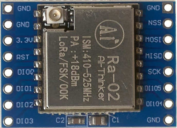
Pin Configuration and Descriptions
The Transceiver LORA typically comes in a module form with the following pin configuration:
| Pin Number | Pin Name | Description |
|---|---|---|
| 1 | GND | Ground connection |
| 2 | VCC | Power supply (1.8V to 3.7V) |
| 3 | MISO | SPI Master-In-Slave-Out |
| 4 | MOSI | SPI Master-Out-Slave-In |
| 5 | SCK | SPI Clock |
| 6 | NSS | SPI Chip Select (Active Low) |
| 7 | DIO0 | Digital I/O Pin 0 (Interrupt/Status) |
| 8 | DIO1 | Digital I/O Pin 1 (Optional Interrupt/Status) |
| 9 | RESET | Reset Pin (Active Low) |
| 10 | ANT | Antenna Connection |
Usage Instructions
How to Use the Component in a Circuit
- Power Supply: Connect the VCC pin to a regulated power source (1.8V to 3.7V) and the GND pin to the ground.
- SPI Communication: Connect the SPI pins (MISO, MOSI, SCK, NSS) to the corresponding SPI pins on your microcontroller.
- Antenna: Attach a suitable antenna to the ANT pin for optimal signal transmission and reception.
- Interrupts: Use the DIO0 and DIO1 pins for handling interrupts or status signals, as required by your application.
- Reset: Connect the RESET pin to the microcontroller or a manual reset button for initializing the module.
Important Considerations and Best Practices
- Antenna Selection: Use an antenna tuned to the operating frequency (e.g., 433 MHz, 868 MHz, or 915 MHz) for maximum range and performance.
- Power Supply: Ensure a stable and noise-free power supply to avoid communication issues.
- Line of Sight: For maximum range, ensure a clear line of sight between the transmitter and receiver.
- Regulatory Compliance: Verify that the operating frequency complies with local regulations.
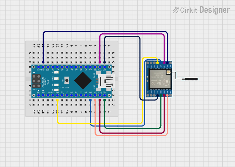
Example: Connecting to an Arduino UNO
Below is an example of how to connect the Transceiver LORA to an Arduino UNO and send data:
Wiring Diagram
| LORA Pin | Arduino UNO Pin |
|---|---|
| VCC | 3.3V |
| GND | GND |
| MISO | Pin 12 |
| MOSI | Pin 11 |
| SCK | Pin 13 |
| NSS | Pin 10 |
| DIO0 | Pin 2 |
| RESET | Pin 9 |
Arduino Code Example
#include <SPI.h>
#include <LoRa.h> // Include the LoRa library

#define NSS 10    // Chip Select pin
#define RESET 9   // Reset pin
#define DIO0 2    // Interrupt pin

void setup() {
  Serial.begin(9600); // Initialize serial communication
  while (!Serial);

  // Initialize LoRa module
  Serial.println("Initializing LoRa...");
  if (!LoRa.begin(915E6)) { // Set frequency to 915 MHz
    Serial.println("LoRa initialization failed!");
    while (1);
  }
  Serial.println("LoRa initialized successfully.");
}

void loop() {
  Serial.println("Sending packet...");
  LoRa.beginPacket();          // Start a new packet
  LoRa.print("Hello, LoRa!");  // Add data to the packet
  LoRa.endPacket();            // Send the packet
  delay(5000);                 // Wait 5 seconds before sending again
}
Troubleshooting and FAQs
Common Issues and Solutions
No Communication Between Devices
- Solution: Ensure both devices are configured to the same frequency and data rate.
- Solution: Check the antenna connection and ensure it matches the operating frequency.
Short Range
- Solution: Verify that there is a clear line of sight between the transmitter and receiver.
- Solution: Use a higher-gain antenna or increase the output power (if configurable).
Module Not Initializing
- Solution: Check the power supply voltage and ensure it is within the specified range.
- Solution: Verify the SPI connections and ensure the NSS pin is correctly configured.
Interference
- Solution: Avoid using the module near other devices operating in the same frequency band.
- Solution: Use a frequency channel with minimal interference.
FAQs
Q: Can I use the Transceiver LORA with a 5V microcontroller?
A: Yes, but you will need a level shifter to convert the 5V logic levels to 3.3V for the LORA module.
Q: What is the maximum range of the Transceiver LORA?
A: The range can reach up to 15 km in ideal conditions (line of sight), but obstacles and interference may reduce this.
Q: Can I use multiple LORA modules in the same area?
A: Yes, but ensure they operate on different channels or use unique addresses to avoid collisions.
Q: Is the Transceiver LORA suitable for high-speed data transmission?
A: No, LORA is optimized for low-power, long-range communication with low data rates (up to 50 kbps).