
How to Use Momentary Switch: Examples, Pinouts, and Specs
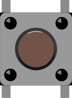
 Design with Momentary Switch in Cirkit Designer
Introduction
The Momentary Switch (Manufacturer Part ID: COM-00097) by SparkFun Electronics is a simple yet versatile electronic component. It is a type of switch that remains in the "on" position only while being pressed and automatically returns to the "off" position when released. This behavior makes it ideal for applications requiring temporary activation, such as doorbells, keyboard keys, or reset buttons in electronic circuits.
Explore Projects Built with Momentary Switch
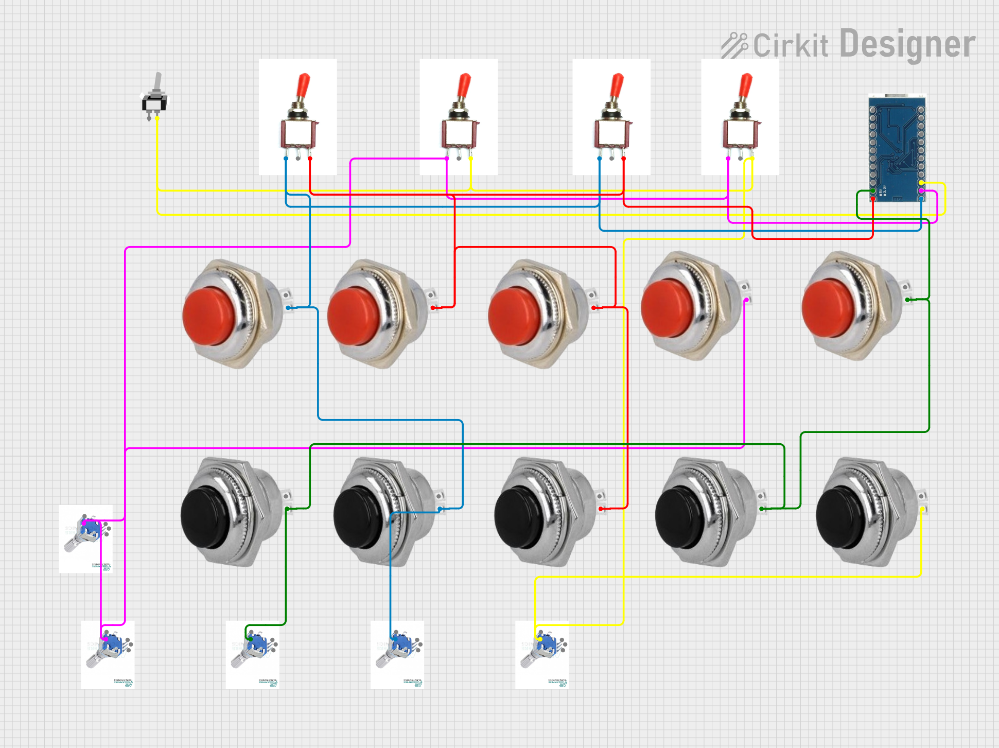 Open Project in Cirkit Designer
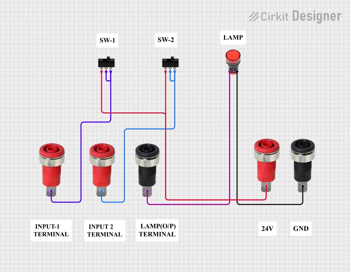 Open Project in Cirkit Designer
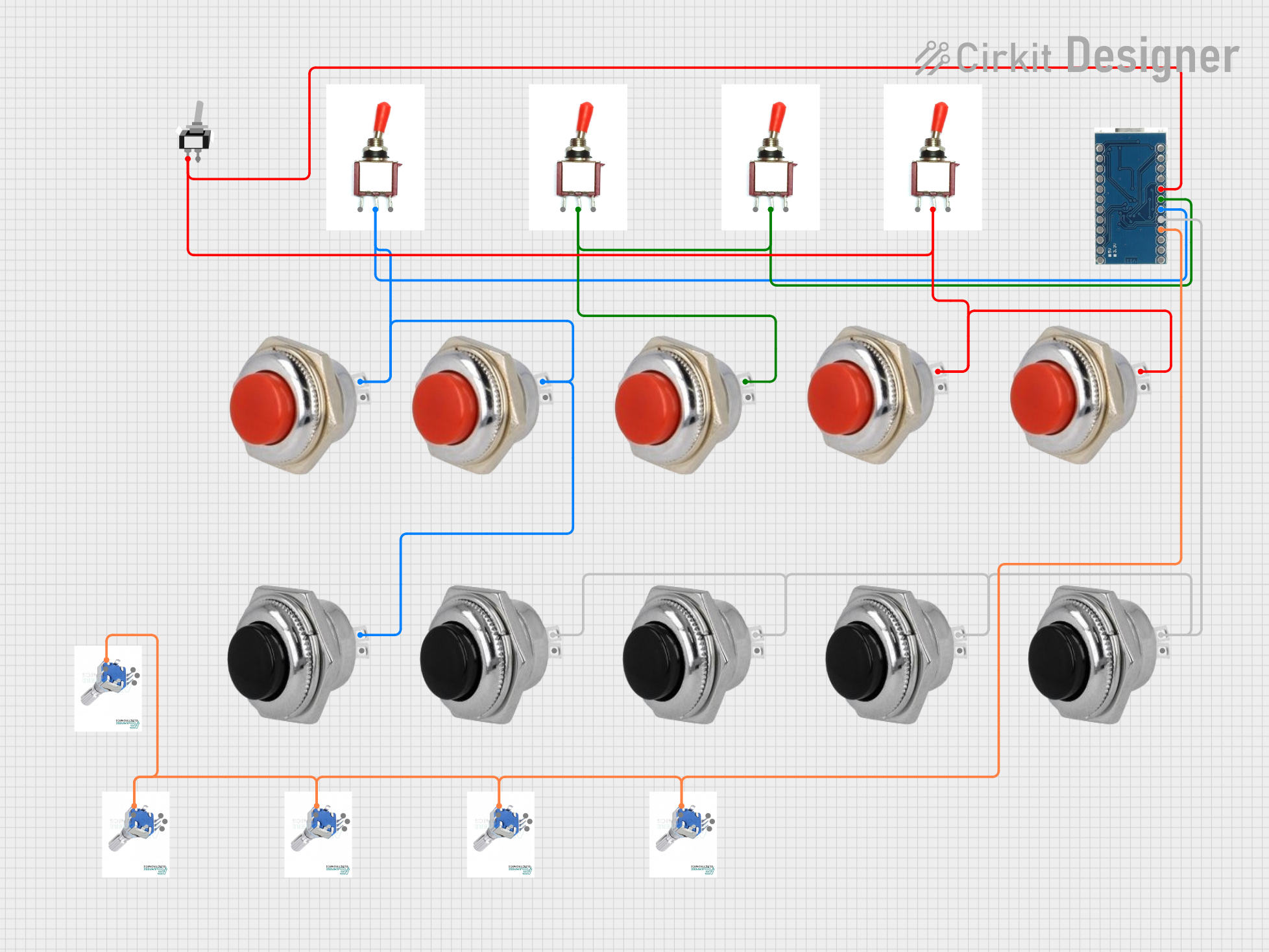 Open Project in Cirkit Designer
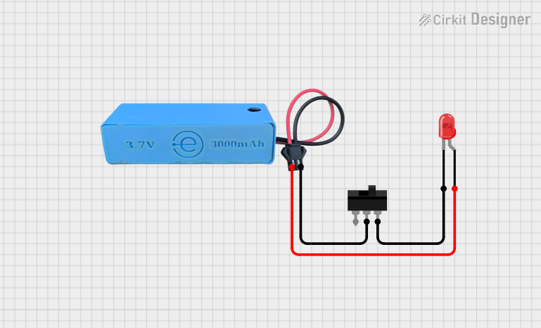 Open Project in Cirkit Designer
Explore Projects Built with Momentary Switch
Open Project in Cirkit DesignerOpen Project in Cirkit DesignerOpen Project in Cirkit DesignerOpen Project in Cirkit DesignerCommon Applications
- Doorbells and buzzers
- Keyboard and gaming controller buttons
- Reset or power buttons in electronic devices
- User input for microcontroller-based projects (e.g., Arduino)
Technical Specifications
Below are the key technical details for the SparkFun Momentary Switch (COM-00097):
| Parameter | Value |
|---|---|
| Manufacturer | SparkFun Electronics |
| Part ID | COM-00097 |
| Switch Type | Momentary (Normally Open) |
| Contact Rating | 50 mA at 12 VDC |
| Contact Resistance | ≤ 100 mΩ |
| Insulation Resistance | ≥ 100 MΩ |
| Operating Temperature | -20°C to +70°C |
| Actuation Force | ~160 gf |
| Dimensions | 6 mm x 6 mm x 5 mm |
| Mounting Type | Through-hole |
Pin Configuration and Descriptions
The momentary switch has four pins, but only two are electrically connected. The other two pins are for mechanical stability. Below is the pin configuration:
| Pin Number | Description |
|---|---|
| Pin 1 | Switch terminal 1 (Normally Open) |
| Pin 2 | Switch terminal 2 (Normally Open) |
| Pin 3 | Mechanical support (not connected) |
| Pin 4 | Mechanical support (not connected) |
Usage Instructions
How to Use the Momentary Switch in a Circuit
- Identify the Active Pins: Use a multimeter to identify the two active pins (Pin 1 and Pin 2). These are the pins that close the circuit when the switch is pressed.
- Connect to Circuit:
- Connect one active pin to the input signal or power source.
- Connect the other active pin to the load or microcontroller input.
- Debounce the Switch: Momentary switches can produce noise or "bouncing" when pressed. Use a capacitor (e.g., 0.1 µF) or software debounce techniques to ensure stable operation.
- Test the Circuit: Press the switch to verify that it activates the desired function.
Example: Connecting to an Arduino UNO
Below is an example of how to connect and use the momentary switch with an Arduino UNO to toggle an LED:
Circuit Diagram
- Connect one active pin of the switch to Digital Pin 2 on the Arduino.
- Connect the other active pin to GND.
- Use a 10 kΩ pull-up resistor between Digital Pin 2 and 5V.
- Connect an LED to Digital Pin 13 with a 220 Ω resistor in series.
Arduino Code
// Define pin numbers
const int switchPin = 2;  // Pin connected to the momentary switch
const int ledPin = 13;    // Pin connected to the LED

// Variable to store the LED state
bool ledState = false;

// Variable to track the last switch state
int lastSwitchState = LOW;

void setup() {
  pinMode(switchPin, INPUT_PULLUP); // Configure switch pin as input with pull-up
  pinMode(ledPin, OUTPUT);          // Configure LED pin as output
  digitalWrite(ledPin, LOW);        // Ensure LED is off initially
}

void loop() {
  // Read the current state of the switch
  int currentSwitchState = digitalRead(switchPin);

  // Check if the switch was pressed (transition from HIGH to LOW)
  if (currentSwitchState == LOW && lastSwitchState == HIGH) {
    delay(50); // Debounce delay
    if (digitalRead(switchPin) == LOW) { // Confirm stable press
      ledState = !ledState; // Toggle the LED state
      digitalWrite(ledPin, ledState ? HIGH : LOW); // Update LED
    }
  }

  // Update the last switch state
  lastSwitchState = currentSwitchState;
}
Important Considerations
- Debouncing: Always account for switch bounce in your design to avoid erratic behavior.
- Current Rating: Do not exceed the 50 mA current rating to prevent damage to the switch.
- Mechanical Stability: Use all four pins for mechanical stability when soldering the switch onto a PCB.
Troubleshooting and FAQs
Common Issues
- Switch Not Responding:
- Ensure the active pins (Pin 1 and Pin 2) are correctly identified and connected.
- Check for loose connections or cold solder joints.
- Erratic Behavior:
- This is likely due to switch bounce. Add a capacitor or implement software debouncing.
- Switch Feels Stuck:
- Inspect for physical damage or debris around the switch.
FAQs
Q: Can I use this switch for high-current applications?
A: No, the switch is rated for a maximum of 50 mA at 12 VDC. For higher currents, use a relay or transistor in conjunction with the switch.
Q: How do I debounce the switch in hardware?
A: Place a small capacitor (e.g., 0.1 µF) across the active pins of the switch to filter out noise.
Q: Can I use this switch with a Raspberry Pi?
A: Yes, the switch can be used with a Raspberry Pi. Connect it to a GPIO pin configured as an input, and use a pull-up or pull-down resistor as needed.
Q: Are the mechanical support pins necessary?
A: While not electrically connected, the mechanical support pins provide stability when soldered to a PCB and should be used for reliable mounting.
This concludes the documentation for the SparkFun Momentary Switch (COM-00097).