
How to Use LED Driver Board for Seeed Studio XIAO: Examples, Pinouts, and Specs
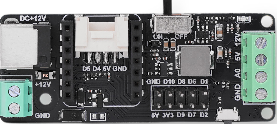
 Design with LED Driver Board for Seeed Studio XIAO in Cirkit Designer
Introduction
The LED Driver Board for Seeed Studio XIAO (Manufacturer Part ID: 105100021) is a specialized circuit board designed to control and drive LED lights. It is fully compatible with the Seeed Studio XIAO microcontroller series, offering efficient power management and advanced control features for various LED applications. This board simplifies the process of integrating LEDs into your projects, making it ideal for hobbyists, students, and professionals alike.
Explore Projects Built with LED Driver Board for Seeed Studio XIAO
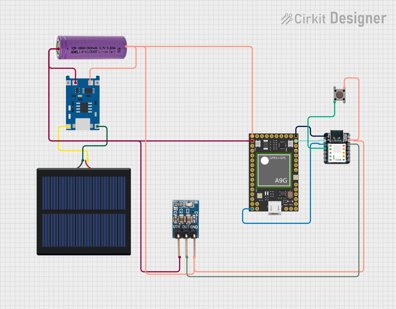 Open Project in Cirkit Designer
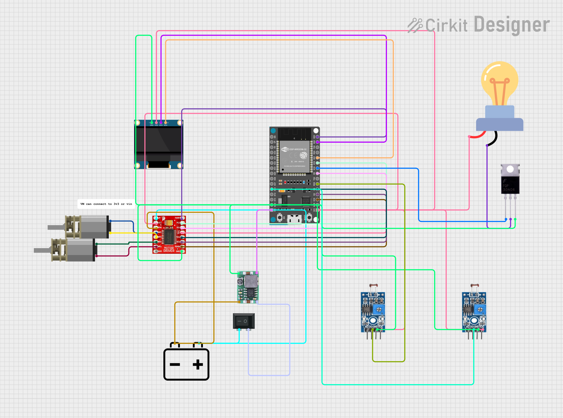 Open Project in Cirkit Designer
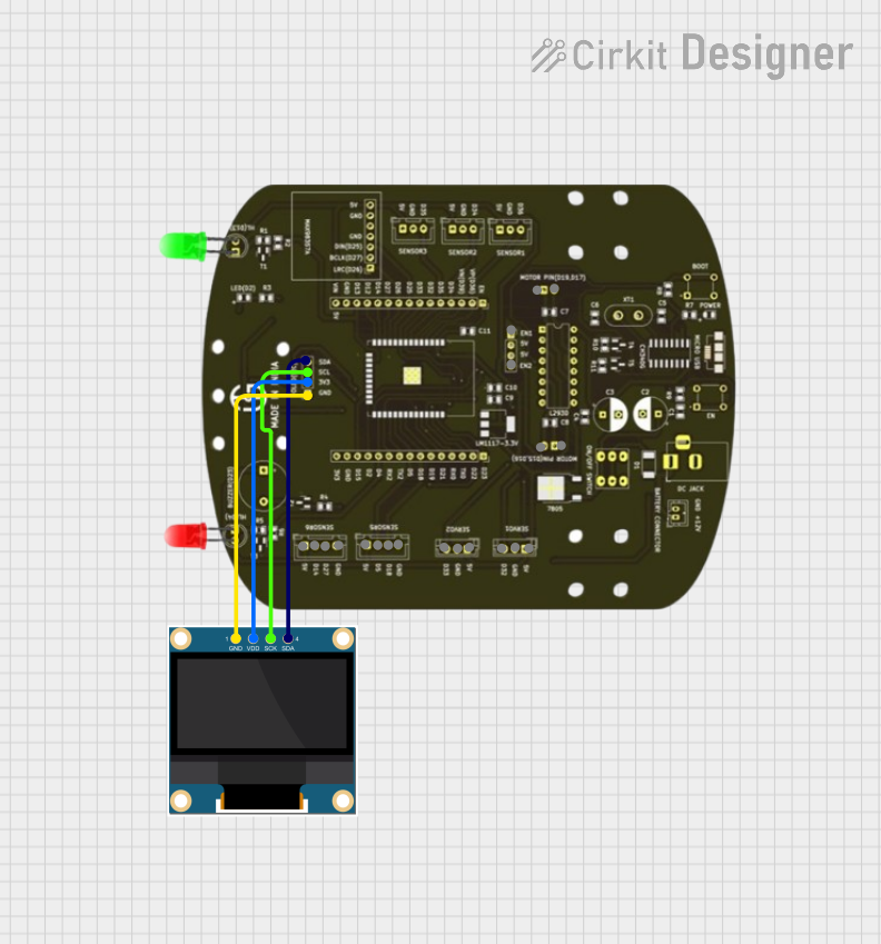 Open Project in Cirkit Designer
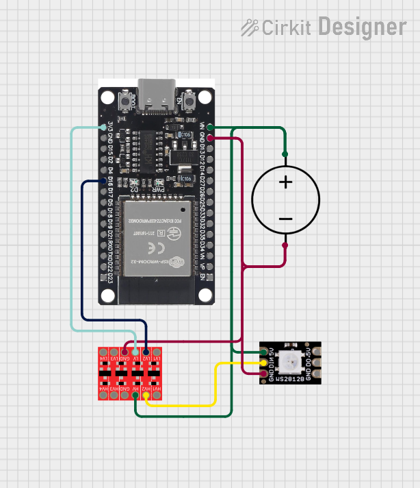 Open Project in Cirkit Designer
Explore Projects Built with LED Driver Board for Seeed Studio XIAO
Open Project in Cirkit DesignerOpen Project in Cirkit DesignerOpen Project in Cirkit DesignerOpen Project in Cirkit DesignerCommon Applications and Use Cases
- LED lighting systems for IoT projects
- RGB LED control for decorative or functional lighting
- Wearable electronics with LED indicators
- Prototyping and testing LED-based circuits
- Low-power LED displays and signage
Technical Specifications
The LED Driver Board is designed to work seamlessly with the Seeed Studio XIAO microcontroller. Below are the key technical details:
General Specifications
| Parameter | Value |
|---|---|
| Input Voltage Range | 3.3V to 5V |
| Output Voltage | 3.3V (regulated) |
| Maximum Output Current | 500mA |
| LED Channels | 4 (PWM control supported) |
| Communication Interface | GPIO (Pulse Width Modulation) |
| Dimensions | 21mm x 17.5mm x 2.5mm |
| Operating Temperature | -40°C to 85°C |
Pin Configuration and Descriptions
The LED Driver Board features a simple pinout for easy integration with the Seeed Studio XIAO. Below is the pin configuration:
| Pin Name | Description |
|---|---|
| VIN | Power input (3.3V to 5V) |
| GND | Ground |
| CH1 | LED Channel 1 (PWM control supported) |
| CH2 | LED Channel 2 (PWM control supported) |
| CH3 | LED Channel 3 (PWM control supported) |
| CH4 | LED Channel 4 (PWM control supported) |
Usage Instructions
How to Use the Component in a Circuit
- Power the Board: Connect the VIN pin to a 3.3V or 5V power source and the GND pin to ground.
- Connect LEDs: Attach the anode (positive terminal) of your LEDs to the respective channel pins (CH1, CH2, CH3, CH4). Connect the cathode (negative terminal) of the LEDs to ground.
- Connect to Seeed Studio XIAO: Use the GPIO pins of the XIAO to send PWM signals to the LED channels for brightness control.
- Program the XIAO: Write a program to control the PWM signals for each channel, enabling precise control of LED brightness and patterns.
Important Considerations and Best Practices
- Ensure the total current drawn by the LEDs does not exceed the maximum output current of 500mA.
- Use appropriate resistors in series with the LEDs to limit current and prevent damage.
- Avoid short circuits between the channel pins and ground.
- For RGB LEDs, connect each color channel (R, G, B) to separate PWM-capable pins for independent control.
Example Code for Arduino UNO-Compatible Seeed Studio XIAO
Below is an example code snippet to control the brightness of LEDs connected to the LED Driver Board using PWM:
// Example code to control LEDs using Seeed Studio XIAO and LED Driver Board

// Define the LED channel pins
#define LED_CH1 3  // Connect CH1 to GPIO pin 3
#define LED_CH2 4  // Connect CH2 to GPIO pin 4
#define LED_CH3 5  // Connect CH3 to GPIO pin 5
#define LED_CH4 6  // Connect CH4 to GPIO pin 6

void setup() {
  // Set LED channel pins as output
  pinMode(LED_CH1, OUTPUT);
  pinMode(LED_CH2, OUTPUT);
  pinMode(LED_CH3, OUTPUT);
  pinMode(LED_CH4, OUTPUT);
}

void loop() {
  // Gradually increase brightness on all channels
  for (int brightness = 0; brightness <= 255; brightness++) {
    analogWrite(LED_CH1, brightness); // Set brightness for CH1
    analogWrite(LED_CH2, brightness); // Set brightness for CH2
    analogWrite(LED_CH3, brightness); // Set brightness for CH3
    analogWrite(LED_CH4, brightness); // Set brightness for CH4
    delay(10); // Small delay for smooth transition
  }

  // Gradually decrease brightness on all channels
  for (int brightness = 255; brightness >= 0; brightness--) {
    analogWrite(LED_CH1, brightness); // Set brightness for CH1
    analogWrite(LED_CH2, brightness); // Set brightness for CH2
    analogWrite(LED_CH3, brightness); // Set brightness for CH3
    analogWrite(LED_CH4, brightness); // Set brightness for CH4
    delay(10); // Small delay for smooth transition
  }
}
Troubleshooting and FAQs
Common Issues Users Might Face
LEDs Not Lighting Up:
- Ensure the VIN pin is connected to a proper power source (3.3V or 5V).
- Check the polarity of the LEDs (anode to channel pin, cathode to ground).
- Verify that the GPIO pins on the XIAO are configured as outputs.
Flickering LEDs:
- Check for loose connections between the board and the LEDs.
- Ensure the PWM frequency is appropriate for the LEDs being used.
Overheating:
- Ensure the total current drawn by the LEDs does not exceed 500mA.
- Use proper resistors to limit the current through each LED.
Solutions and Tips for Troubleshooting
- Use a multimeter to verify voltage levels at the VIN and channel pins.
- Test the board with a single LED before connecting multiple LEDs.
- If using RGB LEDs, ensure each channel is connected to the correct color terminal.
By following this documentation, you can effectively integrate the LED Driver Board for Seeed Studio XIAO into your projects and achieve precise control over your LED lighting systems.