How to Use ATTiny85 Development Board: Examples, Pinouts, and Specs
Introduction
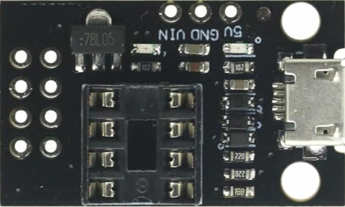
The ATTiny85 Development Board, manufactured by ATMEL Corporation (Part ID: EGBO), is a compact microcontroller board based on the ATtiny85 chip. It is designed for easy prototyping and development of small-scale electronic projects. Despite its small size, the board offers powerful functionality, including multiple I/O pins, programmable memory, and flexible power options.
Explore Projects Built with ATTiny85 Development Board

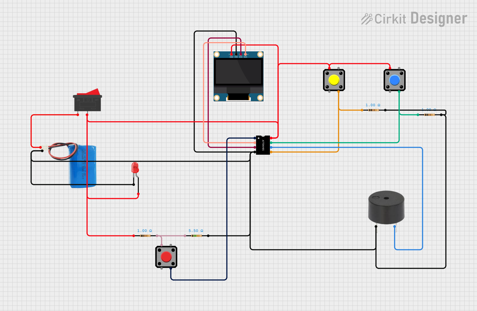
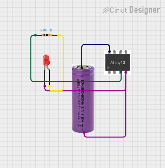

Explore Projects Built with ATTiny85 Development Board
Common Applications and Use Cases
- Wearable electronics
- IoT (Internet of Things) devices
- LED control and lighting projects
- Sensor-based systems
- Small robotics and automation projects
- Battery-powered devices
Technical Specifications
The ATTiny85 Development Board is built to provide a balance of performance and simplicity. Below are its key technical details:
Key Technical Details
- Microcontroller: ATtiny85
- Operating Voltage: 2.7V to 5.5V
- Clock Speed: 8 MHz (internal oscillator, configurable up to 20 MHz with an external crystal)
- Flash Memory: 8 KB (6 KB available for user programs)
- SRAM: 512 bytes
- EEPROM: 512 bytes
- I/O Pins: 6 (5 PWM-capable)
- ADC Channels: 4 (10-bit resolution)
- Communication Protocols: I2C, SPI, and UART (via software)
- Power Supply Options: USB or external battery (3.7V LiPo or 5V source)
- Dimensions: Approximately 25mm x 25mm
Pin Configuration and Descriptions
The ATTiny85 Development Board has a simple pinout, as shown in the table below:
| Pin | Name | Description |
|---|---|---|
| 1 | PB5 (RESET) | Reset pin (active low). Can also be used as a general-purpose I/O pin. |
| 2 | PB3 (ADC3) | Digital I/O or analog input (ADC channel 3). Supports PWM. |
| 3 | PB4 (ADC2) | Digital I/O or analog input (ADC channel 2). Supports PWM. |
| 4 | GND | Ground connection. |
| 5 | PB0 (ADC0) | Digital I/O or analog input (ADC channel 0). Supports PWM. |
| 6 | PB1 (ADC1) | Digital I/O or analog input (ADC channel 1). Supports PWM. |
| 7 | PB2 (SCK) | Digital I/O or SPI clock pin. Can also be used as an analog input. |
| 8 | VCC | Power supply input (2.7V to 5.5V). |
Usage Instructions
The ATTiny85 Development Board is versatile and easy to use in a variety of projects. Below are the steps and best practices for using the board effectively.
How to Use the Component in a Circuit
Powering the Board:
- Connect the board to a USB port or a 3.7V LiPo battery for power.
- Ensure the power supply voltage is within the range of 2.7V to 5.5V.
Programming the Board:
- Use an ISP (In-System Programmer) such as the USBasp or Arduino as ISP to upload code.
- Alternatively, use the Digispark bootloader to program the board via USB.
Connecting Peripherals:
- Use the I/O pins (PB0 to PB5) to connect sensors, LEDs, or other components.
- For analog inputs, connect sensors to ADC pins (PB0 to PB3).
Communication:
- Use I2C or SPI protocols for communication with other devices.
- Software-based UART can be implemented for serial communication.
Important Considerations and Best Practices
- Pin Limitations: The ATTiny85 has only 6 I/O pins, so plan your circuit accordingly.
- Power Consumption: For battery-powered projects, use sleep modes to reduce power consumption.
- Programming Space: Keep your code optimized, as only 6 KB of flash memory is available for user programs.
- Pull-Up Resistors: Enable internal pull-up resistors for input pins if needed.
- External Clock: For higher clock speeds, connect an external crystal oscillator.
Example Code for Arduino IDE
The ATTiny85 can be programmed using the Arduino IDE. Below is an example of a simple LED blink program:
// Blink an LED connected to PB0 (Pin 5 on the ATTiny85)

#define LED_PIN 0  // Define the LED pin (PB0)

void setup() {
  pinMode(LED_PIN, OUTPUT);  // Set PB0 as an output pin
}

void loop() {
  digitalWrite(LED_PIN, HIGH);  // Turn the LED on
  delay(1000);                  // Wait for 1 second
  digitalWrite(LED_PIN, LOW);   // Turn the LED off
  delay(1000);                  // Wait for 1 second
}
To upload this code:
- Install the ATTiny85 board package in the Arduino IDE.
- Select the appropriate board and programmer from the Tools menu.
- Upload the code using your preferred programming method.
Troubleshooting and FAQs
Common Issues and Solutions
The board is not recognized by the computer:
- Ensure the correct drivers are installed for the USB interface.
- Check the USB cable for faults or try a different cable.
Code upload fails:
- Verify that the correct board and programmer are selected in the Arduino IDE.
- Ensure the ATTiny85 is properly connected to the programmer.
The board does not power on:
- Check the power supply voltage (must be between 2.7V and 5.5V).
- Inspect the connections for loose wires or shorts.
I/O pins are not working as expected:
- Confirm that the pins are configured correctly in the code (e.g., input vs. output).
- Check for conflicting pin assignments in your circuit.
FAQs
Q: Can I use the ATTiny85 Development Board with an external crystal oscillator?
A: Yes, the ATTiny85 supports external crystals for higher clock speeds. You will need to configure the fuses accordingly.
Q: How do I reduce power consumption for battery-powered projects?
A: Use the ATTiny85's sleep modes and disable unused peripherals in your code to minimize power usage.
Q: Can I use the ATTiny85 for I2C communication?
A: Yes, the ATTiny85 supports I2C communication using the Wire library in the Arduino IDE.
Q: What is the maximum current output of the I/O pins?
A: Each I/O pin can source or sink up to 40 mA, but it is recommended to limit the current to 20 mA for safe operation.
By following this documentation, you can effectively use the ATTiny85 Development Board in your projects.