How to Use L298N DC motor driver: Examples, Pinouts, and Specs
Introduction
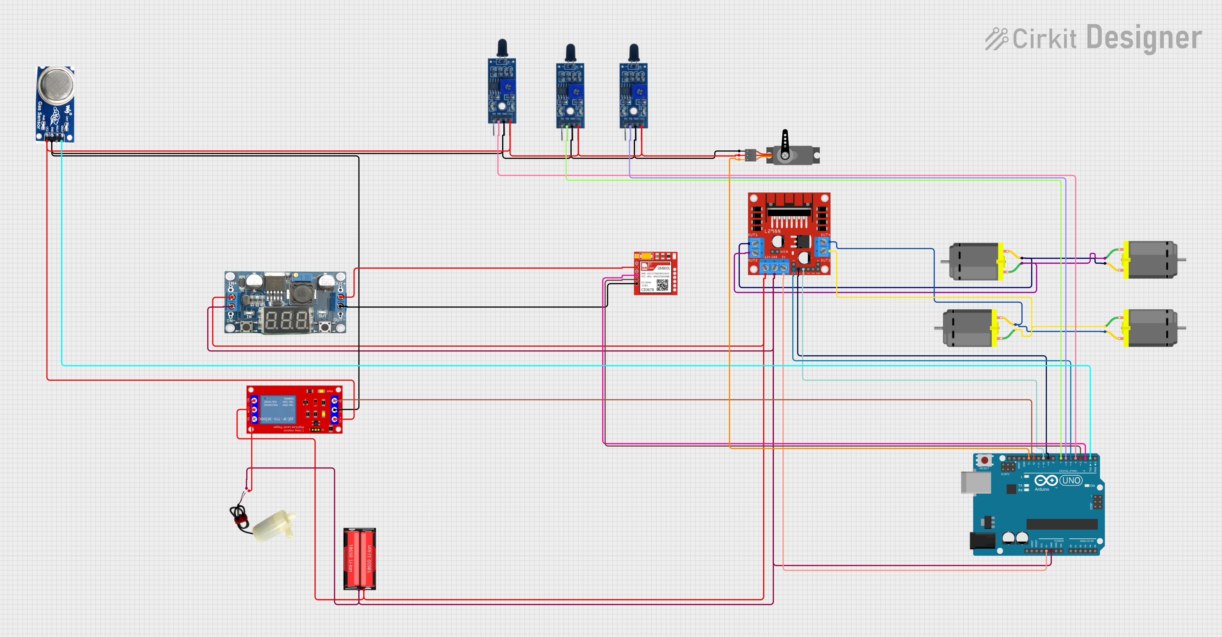
The L298N DC motor driver module is a high-power motor driver perfect for driving DC and stepper motors. It features a dual H-bridge design, allowing for independent control of two DC motors, which means it can control the speed and direction of each one simultaneously. The L298N is widely used in robotics, CNC machines, and other applications where precise motor control is required.
Explore Projects Built with L298N DC motor driver
Explore Projects Built with L298N DC motor driver
Common Applications and Use Cases
- Robotics: driving wheels or tracks
- CNC machines: controlling stepper motors for precise movements
- Electric vehicles: managing propulsion and steering
- Hobby projects: controlling model trains, cars, or boats
Technical Specifications
Key Technical Details
- Operating Voltage (Vcc): 5V to 35V
- Logic Voltage (Vss): 4.5V to 7V
- Peak Output Current (per channel): 2A
- Continuous Output Current (per channel): 1A
- Power Consumption: 36W (max without a heat sink)
- Operating Temperature: -25°C to +130°C
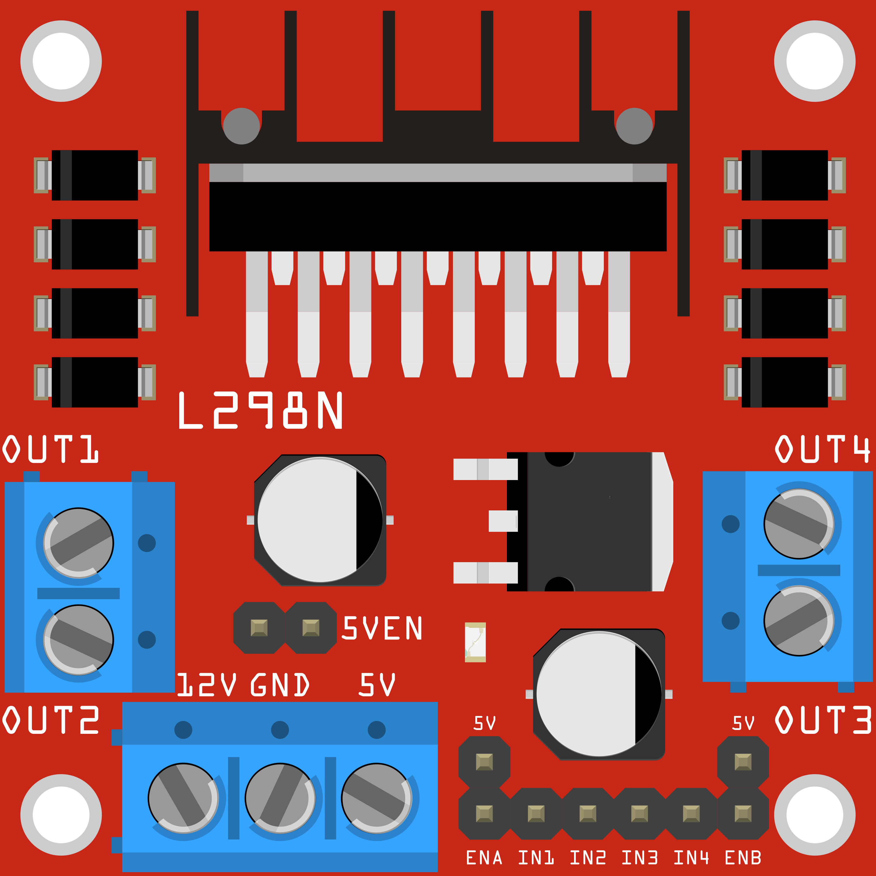
Pin Configuration and Descriptions
| Pin Number | Pin Name | Description |
|---|---|---|
| 1 | OUT1 | Motor A output 1 |
| 2 | OUT2 | Motor A output 2 |
| 3 | OUT3 | Motor B output 1 |
| 4 | OUT4 | Motor B output 2 |
| 5 | Vss | Logic supply voltage (5V from Arduino) |
| 6 | Vcc | Motor supply voltage (up to 35V) |
| 7 | GND | Ground |
| 8 | GND | Ground (for power supply) |
| 9 | ENA | Enable motor A (PWM signal for speed control) |
| 10 | IN1 | Input 1 for motor A direction control |
| 11 | IN2 | Input 2 for motor A direction control |
| 12 | IN3 | Input 3 for motor B direction control |
| 13 | IN4 | Input 4 for motor B direction control |
| 14 | ENB | Enable motor B (PWM signal for speed control) |
| 15 | +5V | Output +5V (if enabled by jumper) |
Usage Instructions
How to Use the Component in a Circuit
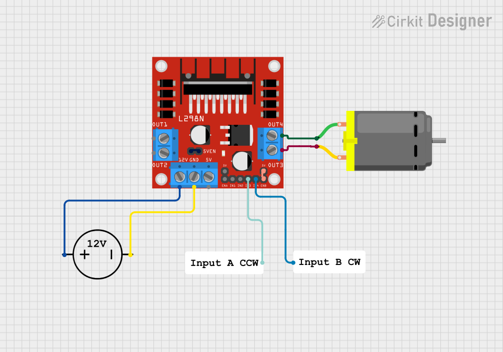
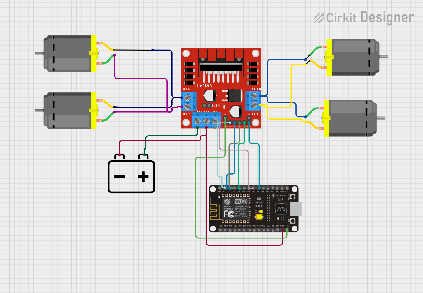
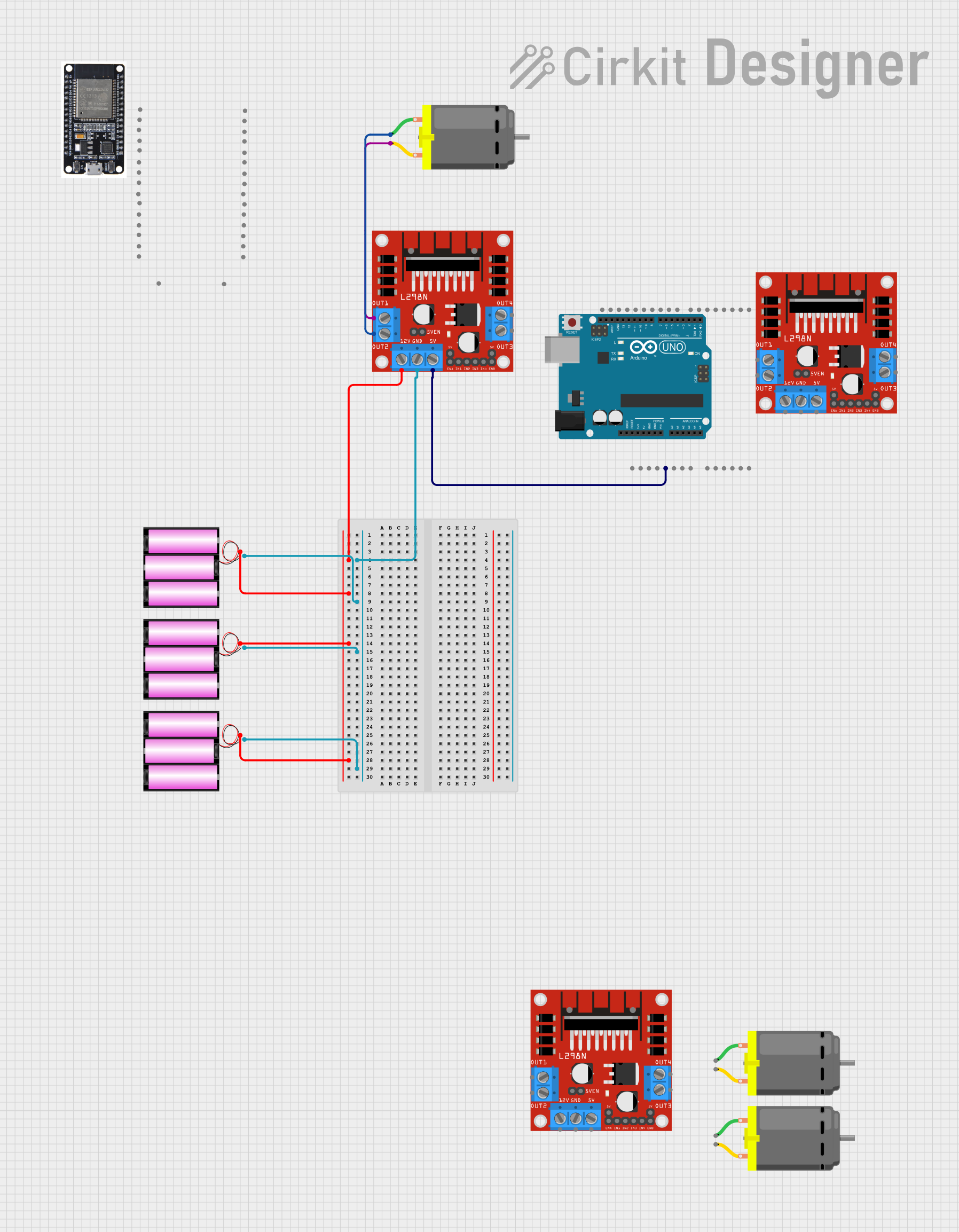
Power Connections:
- Connect the motor supply voltage (up to 35V) to the Vcc pin.
- Connect the ground of the power supply to the GND pin.
- If using the onboard 5V regulator, place a jumper on the 5V_EN pin and connect the +5V pin to the Vss pin.
Logic Connections:
- Connect the Arduino 5V to the Vss pin.
- Connect the Arduino GND to the GND pin.
- Connect the Arduino digital pins to IN1, IN2, IN3, and IN4 for motor direction control.
- Connect the Arduino PWM pins to ENA and ENB for speed control.
Motor Connections:
- Connect the terminals of Motor A to OUT1 and OUT2.
- Connect the terminals of Motor B to OUT3 and OUT4.
Important Considerations and Best Practices
- Ensure the power supply voltage does not exceed the maximum rating of 35V.
- Do not exceed the peak output current of 2A per channel to prevent damage.
- Use a heat sink if operating near the maximum power consumption.
- Always use PWM signals on ENA and ENB for speed control to avoid damaging the motors.
- Ensure proper decoupling of the power supply to prevent noise and voltage spikes.
Example Arduino Code
// Define L298N Dual H-Bridge Motor Controller Pins
#define ENA 9
#define IN1 8
#define IN2 7
#define IN3 6
#define IN4 5
#define ENB 3

// Initialize the motor control pins as outputs
void setup() {
  pinMode(ENA, OUTPUT);
  pinMode(IN1, OUTPUT);
  pinMode(IN2, OUTPUT);
  pinMode(IN3, OUTPUT);
  pinMode(IN4, OUTPUT);
  pinMode(ENB, OUTPUT);
}

// Function to control motor direction and speed
void controlMotor(int motor, int speed, bool direction) {
  digitalWrite(motor == 1 ? IN1 : IN3, direction);
  digitalWrite(motor == 1 ? IN2 : IN4, !direction);
  analogWrite(motor == 1 ? ENA : ENB, speed);
}

// Main program loop
void loop() {
  // Set Motor A to spin in one direction at full speed
  controlMotor(1, 255, true);
  delay(2000);

  // Set Motor A to spin in the opposite direction at half speed
  controlMotor(1, 127, false);
  delay(2000);

  // Set Motor B to spin in one direction at a quarter speed
  controlMotor(2, 63, true);
  delay(2000);

  // Set Motor B to spin in the opposite direction at three quarters speed
  controlMotor(2, 191, false);
  delay(2000);
}
Troubleshooting and FAQs
Common Issues Users Might Face
- Motor not spinning: Check power supply connections, ensure the input pins are receiving the correct signals, and verify that the PWM signal is being sent to ENA or ENB.
- Overheating: Ensure that the current draw is within the specified limits and consider adding a heat sink.
- Inconsistent motor speeds: Check for loose connections and ensure PWM signals are stable.
Solutions and Tips for Troubleshooting
- Double-check wiring against the pin configuration table.
- Use a multimeter to verify the voltage at the motor outputs.
- Test the L298N module with a simple code to ensure it's functioning correctly.
- If using long wires, keep them as short as possible to minimize voltage drop and interference.
FAQs
Q: Can I control stepper motors with the L298N? A: Yes, the L298N can be used to control bipolar stepper motors.
Q: What should I do if my motor draws more than 2A? A: You should use an external heat sink or consider a motor driver capable of handling higher currents.
Q: Can I use the L298N without an Arduino? A: Yes, any microcontroller with digital output pins can be used to control the L298N.
Q: How do I reverse the motor direction? A: Reverse the logic levels on IN1 and IN2 for Motor A or IN3 and IN4 for Motor B.