Cirkit Designer Logo
Cirkit Designer
Your all-in-one circuit design IDE
Home / 
Component Documentation

How to Use SparkFun micro:bit Breakout: Examples, Pinouts, and Specs

Image of SparkFun micro:bit Breakout
Cirkit Designer LogoDesign with SparkFun micro:bit Breakout in Cirkit Designer

Introduction

The SparkFun micro:bit Breakout is a versatile breakout board tailored for the BBC micro:bit development board. This breakout board extends the capabilities of the micro:bit by providing easy access to all of its pins and adding extra features like an OLED display and buttons. It is ideal for educational purposes, prototyping, and hobbyist projects, allowing users to explore a wide range of electronic concepts and applications.

Explore Projects Built with SparkFun micro:bit Breakout

Use Cirkit Designer to design, explore, and prototype these projects online. Some projects support real-time simulation. Click "Open Project" to start designing instantly!
Adafruit Crickit Controlled Robotics Platform with Micro:bit
Image of Circuit Design for Recyclo-Bot: A project utilizing SparkFun micro:bit Breakout in a practical application
This circuit is designed to control multiple motors and servos using an Adafruit Crickit for microbit as the main controller, interfaced with a micro bit microcontroller. It includes two yellow hobby gear motors, two 9G micro servos, and two standard servos, all powered and controlled by the Crickit board. Additionally, there is a 0.96" OLED display for output and a piezo sensor, likely for input, connected to the Crickit, which is programmed via the micro bit.
Cirkit Designer LogoOpen Project in Cirkit Designer
Touch-Interactive Distance Measurement System with Visual and Audio Feedback
Image of DIBH project: A project utilizing SparkFun micro:bit Breakout in a practical application
This is a microcontroller-based interactive circuit featuring touch and ultrasonic sensors for input, and LEDs, a buzzer, and an OLED display for output. It is powered by a 9V battery with a voltage regulator for stable operation, and includes a toggle switch for power control. The actual behavior of the circuit is determined by the embedded code, which is currently a placeholder for further development.
Cirkit Designer LogoOpen Project in Cirkit Designer
Bluetooth-Controlled Robotic Vehicle with Ultrasonic Obstacle Detection and Motion Sensing
Image of 아두이노 드론: A project utilizing SparkFun micro:bit Breakout in a practical application
This circuit features a SparkFun Pro Micro microcontroller interfaced with an L298N DC motor driver to control two DC motors, an HC-SR04 ultrasonic sensor for distance measurement, a Bluetooth module HM-10 for wireless communication, and an MPU-6050 for motion tracking. The Pro Micro is responsible for processing sensor data and managing motor speeds and directions via the motor driver. Power is supplied by a 5V battery connected to the Pro Micro and a separate battery case providing 12V to the motor driver.
Cirkit Designer LogoOpen Project in Cirkit Designer
Battery-Powered Game Controller with SparkFun Pro Micro and Raspberry Pi 4B
Image of Raspberry Pi handheld: A project utilizing SparkFun micro:bit Breakout in a practical application
This circuit is a custom game controller featuring a SparkFun Pro Micro microcontroller, multiple tactile pushbuttons, and two analog joysticks. The Pro Micro reads inputs from the buttons and joysticks, processes them, and sends the corresponding gamepad signals. Additionally, a Raspberry Pi 4B is powered by a Pisugar S Pro battery module.
Cirkit Designer LogoOpen Project in Cirkit Designer

Explore Projects Built with SparkFun micro:bit Breakout

Use Cirkit Designer to design, explore, and prototype these projects online. Some projects support real-time simulation. Click "Open Project" to start designing instantly!
Image of Circuit Design for Recyclo-Bot: A project utilizing SparkFun micro:bit Breakout in a practical application
Adafruit Crickit Controlled Robotics Platform with Micro:bit
This circuit is designed to control multiple motors and servos using an Adafruit Crickit for microbit as the main controller, interfaced with a micro bit microcontroller. It includes two yellow hobby gear motors, two 9G micro servos, and two standard servos, all powered and controlled by the Crickit board. Additionally, there is a 0.96" OLED display for output and a piezo sensor, likely for input, connected to the Crickit, which is programmed via the micro bit.
Cirkit Designer LogoOpen Project in Cirkit Designer
Image of DIBH project: A project utilizing SparkFun micro:bit Breakout in a practical application
Touch-Interactive Distance Measurement System with Visual and Audio Feedback
This is a microcontroller-based interactive circuit featuring touch and ultrasonic sensors for input, and LEDs, a buzzer, and an OLED display for output. It is powered by a 9V battery with a voltage regulator for stable operation, and includes a toggle switch for power control. The actual behavior of the circuit is determined by the embedded code, which is currently a placeholder for further development.
Cirkit Designer LogoOpen Project in Cirkit Designer
Image of 아두이노 드론: A project utilizing SparkFun micro:bit Breakout in a practical application
Bluetooth-Controlled Robotic Vehicle with Ultrasonic Obstacle Detection and Motion Sensing
This circuit features a SparkFun Pro Micro microcontroller interfaced with an L298N DC motor driver to control two DC motors, an HC-SR04 ultrasonic sensor for distance measurement, a Bluetooth module HM-10 for wireless communication, and an MPU-6050 for motion tracking. The Pro Micro is responsible for processing sensor data and managing motor speeds and directions via the motor driver. Power is supplied by a 5V battery connected to the Pro Micro and a separate battery case providing 12V to the motor driver.
Cirkit Designer LogoOpen Project in Cirkit Designer
Image of Raspberry Pi handheld: A project utilizing SparkFun micro:bit Breakout in a practical application
Battery-Powered Game Controller with SparkFun Pro Micro and Raspberry Pi 4B
This circuit is a custom game controller featuring a SparkFun Pro Micro microcontroller, multiple tactile pushbuttons, and two analog joysticks. The Pro Micro reads inputs from the buttons and joysticks, processes them, and sends the corresponding gamepad signals. Additionally, a Raspberry Pi 4B is powered by a Pisugar S Pro battery module.
Cirkit Designer LogoOpen Project in Cirkit Designer

Common Applications and Use Cases

  • Educational tools for learning electronics and programming
  • Prototyping IoT (Internet of Things) devices
  • User interfaces with buttons and displays
  • Robotics and control systems
  • Wearable electronics

Technical Specifications

Key Technical Details

  • Voltage: 3.3V (supplied by the micro:bit)
  • Current: Varies depending on connected peripherals
  • Power Ratings: Dependent on the micro:bit and external power sources
  • Display: OLED for visual output
  • Buttons: Additional input interfaces

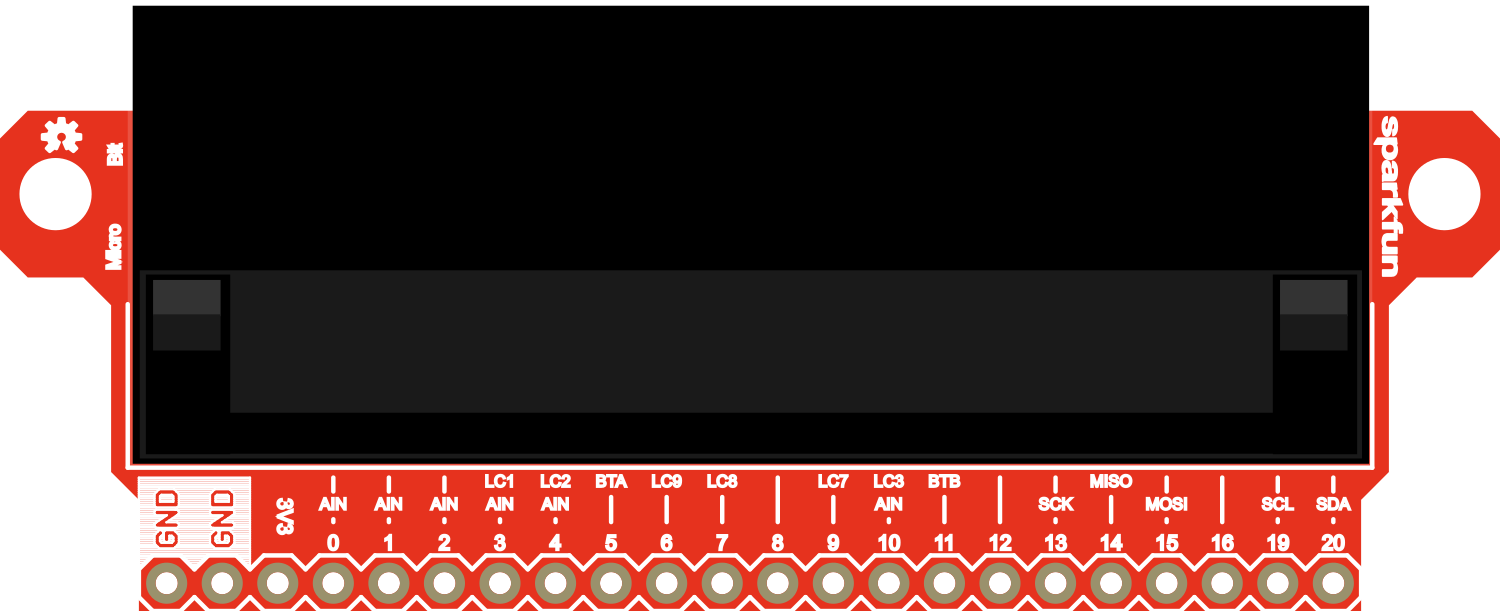
Pin Configuration and Descriptions

Pin Number Name Description
1 VOUT 3.3V power output from the micro:bit
2 GND Ground connection
3-20 P0-P19 General purpose I/O pins
21 3V3 3.3V power supply input
22 RESET Reset pin for the micro:bit

Usage Instructions

How to Use the Component in a Circuit

  1. Connecting the micro:bit:

    • Align the edge connector of the micro:bit with the female header on the breakout board and gently slide it in to make a secure connection.
  2. Powering the Breakout:

    • The breakout board is powered through the micro:bit. Ensure that the micro:bit is powered via USB or an external battery pack.
  3. Accessing Pins:

    • Use jumper wires to connect the breakout pins to other components or a breadboard for prototyping.
  4. Using the OLED Display:

    • The OLED display can be controlled via the I2C protocol. Use the appropriate micro:bit libraries to send data to the display.
  5. Interfacing with Buttons:

    • The additional buttons on the breakout can be read as digital inputs. Connect them to the micro:bit's I/O pins and monitor their state in your code.

Important Considerations and Best Practices

  • Always disconnect the micro:bit from power sources before attaching or detaching it from the breakout board.
  • Be mindful of the power requirements of external components to avoid overloading the micro:bit's power output.
  • Use anti-static precautions when handling the breakout board to prevent damage to sensitive components.

Troubleshooting and FAQs

Common Issues Users Might Face

  • Display Not Working:

    • Check the I2C connections and ensure that the correct pins are used.
    • Verify that the OLED display libraries are correctly included in your code.
  • Buttons Not Responding:

    • Ensure that the buttons are properly connected to the I/O pins.
    • Check for any loose connections or shorts in the circuit.
  • Power Issues:

    • Confirm that the micro:bit is correctly powered and that the power LED is lit.
    • If using external power sources, ensure they are within the recommended voltage range.

Solutions and Tips for Troubleshooting

  • Double-check all connections and ensure they are secure.
  • Review your code for any potential errors or misconfigurations.
  • Reset the micro:bit if it becomes unresponsive.

FAQs

Q: Can I power external components through the breakout board? A: Yes, but ensure that the power requirements do not exceed the micro:bit's capabilities.

Q: Is the breakout board compatible with all versions of the micro:bit? A: The breakout board is designed to be compatible with the standard micro:bit form factor. Check the manufacturer's specifications for version compatibility.

Q: How do I program the micro:bit when it's connected to the breakout board? A: You can program the micro:bit using the standard USB connection. The breakout board does not interfere with the programming process.

Example Code for Arduino UNO

// Example code to interface with the OLED display on the SparkFun micro:bit Breakout
#include <Wire.h>
#include <Adafruit_GFX.h>
#include <Adafruit_SSD1306.h>

// OLED display TWI address
#define OLED_ADDR   0x3C
// Reset pin not used but required for library
#define OLED_RESET  -1

Adafruit_SSD1306 display(128, 64, &Wire, OLED_RESET);

void setup() {
  // Initialize with the I2C addr 0x3C (for the 128x64)
  if(!display.begin(SSD1306_SWITCHCAPVCC, OLED_ADDR)) {
    Serial.println(F("SSD1306 allocation failed"));
    for(;;); // Don't proceed, loop forever
  }
  display.display();
  delay(2000); // Pause for 2 seconds

  // Clear the buffer
  display.clearDisplay();
  display.setTextSize(1);      // Normal 1:1 pixel scale
  display.setTextColor(SSD1306_WHITE); // Draw white text
  display.setCursor(0,0);     // Start at top-left corner
  display.print(F("Hello, micro:bit!"));
  display.display();
}

void loop() {
  // Nothing to do here
}

Please note that the above example is for illustration purposes and is written for an Arduino UNO, which has a similar I2C interface to the micro:bit. When using the SparkFun micro:bit Breakout, you will need to use the micro:bit's programming environment and libraries.