How to Use ESP32-D0WDQ6: Examples, Pinouts, and Specs
Introduction
The ESP32-D0WDQ6 is a versatile and powerful microcontroller unit (MCU) developed by Espressif Systems, featuring integrated Wi-Fi and Bluetooth capabilities. This chip is designed for a wide range of Internet of Things (IoT) applications, including smart home devices, wearable electronics, and wireless sensor networks. Its dual-core processor and rich set of peripherals make it suitable for complex and demanding tasks.
Explore Projects Built with ESP32-D0WDQ6
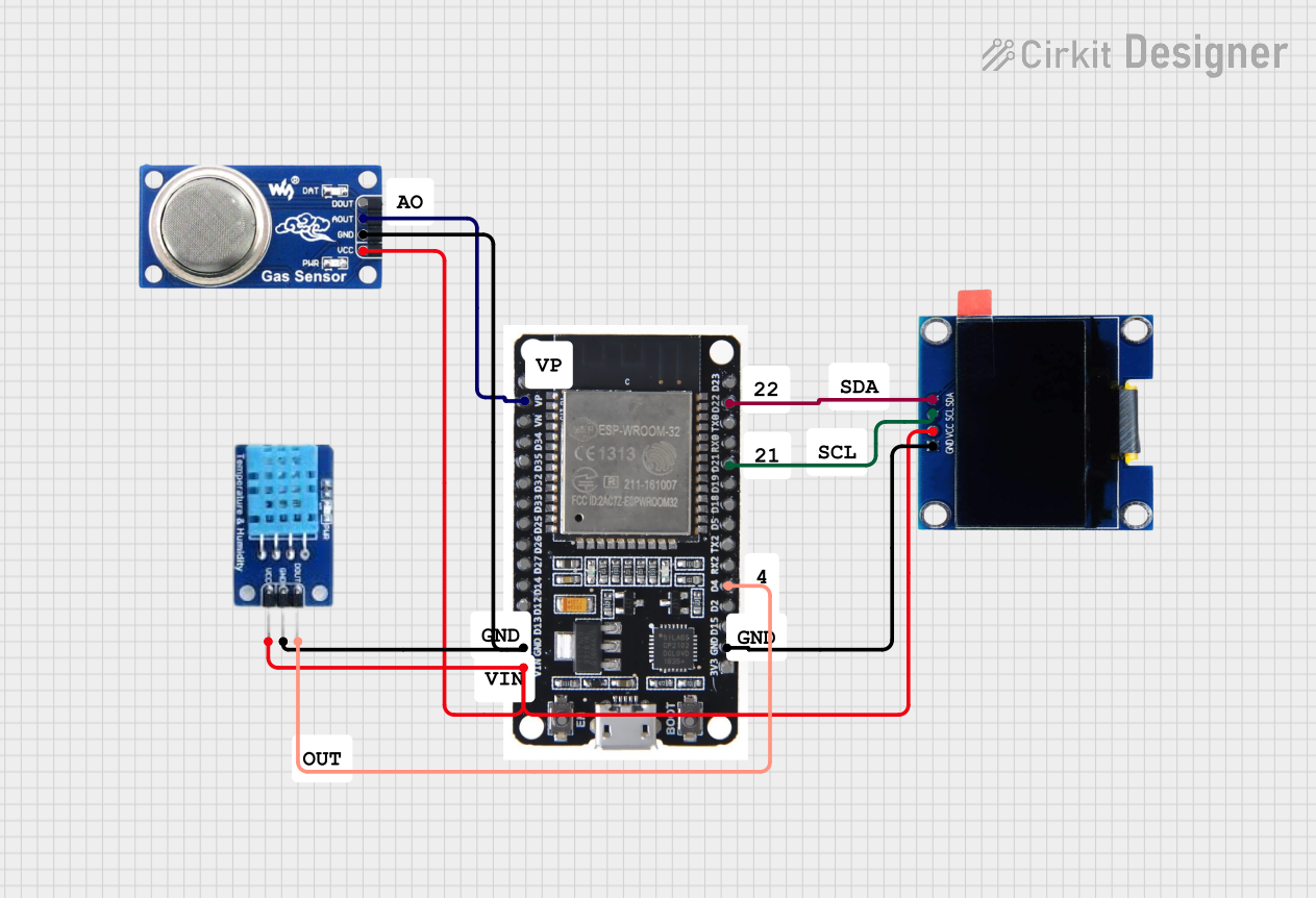


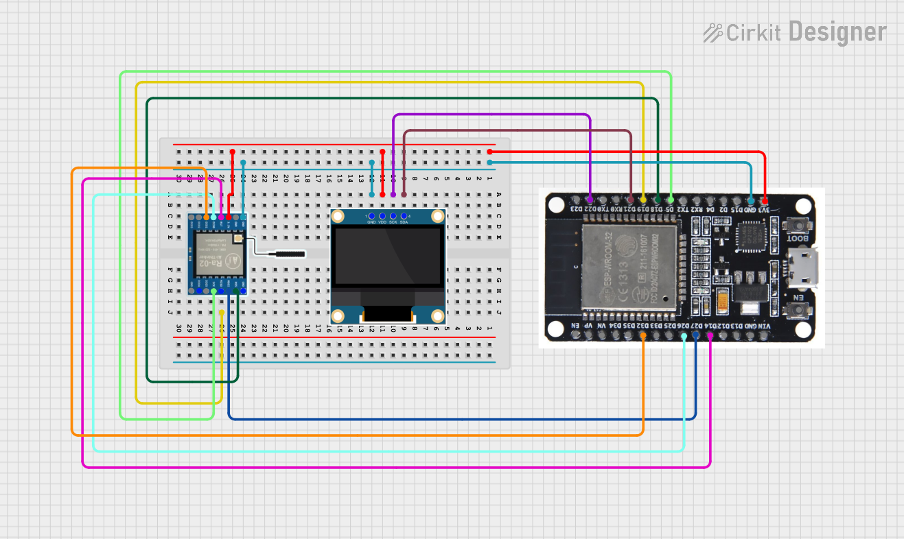
Explore Projects Built with ESP32-D0WDQ6
Common Applications and Use Cases
- Smart Home Devices (e.g., lighting, security systems)
- Wearable Technology
- Wireless Sensor Networks
- Internet of Things (IoT) Devices
- Low-power Embedded Systems
Technical Specifications
Key Technical Details
- CPU: Xtensa® 32-bit LX6 dual-core processor
- Operating Voltage: 2.2V to 3.6V
- IO Voltage: 3.3V
- Clock Frequency: Up to 240 MHz
- Flash Memory: Up to 16 MB
- SRAM: 520 KB
- Wi-Fi: 802.11 b/g/n
- Bluetooth: v4.2 BR/EDR and BLE
- Temperature Range: -40°C to 125°C
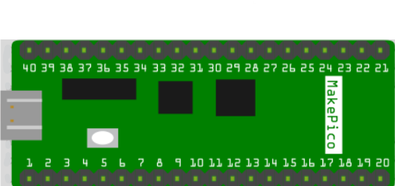
Pin Configuration and Descriptions
| Pin Number | Name | Type | Description |
|---|---|---|---|
| 1 | GND | P | Ground |
| 2 | 3V3 | P | 3.3V Power Supply |
| 3 | EN | I | Chip Enable. Active high. |
| ... | ... | ... | ... |
| n | IOx | I/O | General Purpose Input/Output x |
(P: Power, I: Input, O: Output, I/O: Input/Output)
Usage Instructions
How to Use the Component in a Circuit
Power Supply: Ensure that the ESP32-D0WDQ6 is powered with a stable 3.3V supply. Exceeding the voltage rating can damage the chip.
Boot Mode Configuration: To boot from the internal flash, the GPIO0 must be pulled high on reset.
Antenna Connection: For optimal Wi-Fi and Bluetooth performance, connect an appropriate antenna to the chip's antenna pins.
Programming: The ESP32-D0WDQ6 can be programmed via the serial interface using the UART bootloader or through the JTAG interface.
Important Considerations and Best Practices
- Use decoupling capacitors close to the power pins to filter out noise.
- Ensure that the PCB design follows Espressif's guidelines for trace impedance and antenna design.
- Avoid running high-speed traces or noisy signals near the antenna to minimize interference.
- Implement proper ESD protection, especially for the GPIO pins.
Troubleshooting and FAQs
Common Issues Users Might Face
- Power Issues: If the ESP32 does not power up, check the power supply and connections.
- Boot Failure: Ensure that the boot mode configuration is correct.
- Wi-Fi/Bluetooth Connectivity: If experiencing connectivity issues, verify the antenna connections and check for sources of interference.
Solutions and Tips for Troubleshooting
- Use a multimeter to verify the power supply voltage and pin connections.
- Check the soldering of the ESP32-D0WDQ6 for cold joints or bridges.
- Use the Espressif IDF tools for logging and debugging to diagnose software issues.
FAQs
Q: Can the ESP32-D0WDQ6 be used with Arduino IDE? A: Yes, the ESP32-D0WDQ6 is supported by the Arduino IDE. You will need to install the ESP32 board package.
Q: What is the maximum operating temperature for the ESP32-D0WDQ6? A: The maximum operating temperature is 125°C.
Q: How can I update the firmware on the ESP32-D0WDQ6? A: Firmware can be updated using the UART bootloader or over-the-air (OTA) updates.
Example Code for Arduino UNO
Below is a simple example of how to blink an LED connected to the ESP32-D0WDQ6 using the Arduino IDE.
// Define the LED pin
const int ledPin = 2; // Use GPIO2 for the LED

// Setup function runs once at the start
void setup() {
  // Initialize the LED pin as an output
  pinMode(ledPin, OUTPUT);
}

// Loop function runs over and over again
void loop() {
  digitalWrite(ledPin, HIGH);   // Turn the LED on
  delay(1000);                  // Wait for a second
  digitalWrite(ledPin, LOW);    // Turn the LED off
  delay(1000);                  // Wait for another second
}
Remember to configure the Arduino IDE with the correct board settings for the ESP32-D0WDQ6 before uploading the code.