Cirkit Designer Logo
Cirkit Designer
Your all-in-one circuit design IDE
Home / 
Component Documentation

How to Use ESP32: Examples, Pinouts, and Specs

Image of ESP32
Cirkit Designer LogoDesign with ESP32 in Cirkit Designer

Introduction

The ESP32, manufactured by THINGS KIT MINI with the part ID NODEMCU, is a low-cost, low-power system on a chip (SoC) designed for IoT applications. It integrates Wi-Fi and Bluetooth capabilities, making it a versatile and powerful solution for a wide range of projects. The ESP32 is widely used in smart home devices, wearable electronics, industrial automation, and other applications requiring wireless connectivity and efficient processing.

Explore Projects Built with ESP32

Use Cirkit Designer to design, explore, and prototype these projects online. Some projects support real-time simulation. Click "Open Project" to start designing instantly!
ESP32-Based Sensor Monitoring System with OLED Display and E-Stop
Image of MVP_design: A project utilizing ESP32 in a practical application
This circuit features an ESP32 microcontroller that interfaces with a variety of sensors and output devices. It is powered by a Lipo battery through a buck converter, ensuring a stable voltage supply. The ESP32 collects data from a DHT11 temperature and humidity sensor and a vibration sensor, controls a buzzer, and displays information on an OLED screen. An emergency stop (E Stop) is connected for safety purposes, allowing the system to be quickly deactivated.
Cirkit Designer LogoOpen Project in Cirkit Designer
ESP32-Based NTP Clock with DHT22 Temperature Sensor and WS2812 LED Matrix Display
Image of date time and temperature display : A project utilizing ESP32 in a practical application
This circuit features an ESP32 Devkit V1 microcontroller connected to a DHT22 temperature and humidity sensor and an 8x8 WS2812 RGB LED matrix. The ESP32 reads temperature data from the DHT22 sensor and displays the current date, time, and temperature on the LED matrix, with date and time synchronized via NTP (Network Time Protocol). The ESP32 provides power to both the DHT22 and the LED matrix and communicates with the DHT22 via GPIO 4 and with the LED matrix via GPIO 5.
Cirkit Designer LogoOpen Project in Cirkit Designer
ESP32-Based Environmental Monitoring System with Water Flow Sensing
Image of Water: A project utilizing ESP32 in a practical application
This circuit features an ESP32 Devkit V1 microcontroller connected to a DHT22 temperature and humidity sensor and a water flow sensor. The ESP32 reads environmental data from the DHT22 via a digital input pin (D33) and monitors water flow through the water flow sensor connected to another digital input pin (D23). The ESP32 is powered through its VIN pin, and both sensors are powered by the ESP32's 3V3 output, with common ground connections.
Cirkit Designer LogoOpen Project in Cirkit Designer
ESP32-Based Smart Weather Station with Wi-Fi Connectivity
Image of flowchart 3D: A project utilizing ESP32 in a practical application
This circuit features an ESP32 microcontroller interfacing with various sensors and modules, including a DHT22 temperature and humidity sensor, an ESP32 CAM for image capture, an I2C LCD screen for display, a load cell with an HX711 interface for weight measurement, and a buzzer for audio alerts. The ESP32 handles data acquisition, processing, and communication with these peripherals to create a multi-functional monitoring and alert system.
Cirkit Designer LogoOpen Project in Cirkit Designer

Explore Projects Built with ESP32

Use Cirkit Designer to design, explore, and prototype these projects online. Some projects support real-time simulation. Click "Open Project" to start designing instantly!
Image of MVP_design: A project utilizing ESP32 in a practical application
ESP32-Based Sensor Monitoring System with OLED Display and E-Stop
This circuit features an ESP32 microcontroller that interfaces with a variety of sensors and output devices. It is powered by a Lipo battery through a buck converter, ensuring a stable voltage supply. The ESP32 collects data from a DHT11 temperature and humidity sensor and a vibration sensor, controls a buzzer, and displays information on an OLED screen. An emergency stop (E Stop) is connected for safety purposes, allowing the system to be quickly deactivated.
Cirkit Designer LogoOpen Project in Cirkit Designer
Image of date time and temperature display : A project utilizing ESP32 in a practical application
ESP32-Based NTP Clock with DHT22 Temperature Sensor and WS2812 LED Matrix Display
This circuit features an ESP32 Devkit V1 microcontroller connected to a DHT22 temperature and humidity sensor and an 8x8 WS2812 RGB LED matrix. The ESP32 reads temperature data from the DHT22 sensor and displays the current date, time, and temperature on the LED matrix, with date and time synchronized via NTP (Network Time Protocol). The ESP32 provides power to both the DHT22 and the LED matrix and communicates with the DHT22 via GPIO 4 and with the LED matrix via GPIO 5.
Cirkit Designer LogoOpen Project in Cirkit Designer
Image of Water: A project utilizing ESP32 in a practical application
ESP32-Based Environmental Monitoring System with Water Flow Sensing
This circuit features an ESP32 Devkit V1 microcontroller connected to a DHT22 temperature and humidity sensor and a water flow sensor. The ESP32 reads environmental data from the DHT22 via a digital input pin (D33) and monitors water flow through the water flow sensor connected to another digital input pin (D23). The ESP32 is powered through its VIN pin, and both sensors are powered by the ESP32's 3V3 output, with common ground connections.
Cirkit Designer LogoOpen Project in Cirkit Designer
Image of flowchart 3D: A project utilizing ESP32 in a practical application
ESP32-Based Smart Weather Station with Wi-Fi Connectivity
This circuit features an ESP32 microcontroller interfacing with various sensors and modules, including a DHT22 temperature and humidity sensor, an ESP32 CAM for image capture, an I2C LCD screen for display, a load cell with an HX711 interface for weight measurement, and a buzzer for audio alerts. The ESP32 handles data acquisition, processing, and communication with these peripherals to create a multi-functional monitoring and alert system.
Cirkit Designer LogoOpen Project in Cirkit Designer

Common Applications and Use Cases

  • IoT Devices: Smart home automation, environmental monitoring, and connected appliances.
  • Wearables: Fitness trackers, health monitoring devices, and smartwatches.
  • Industrial Automation: Wireless sensor networks, machine monitoring, and control systems.
  • Prototyping and Development: Ideal for hobbyists and engineers building connected projects.

Technical Specifications

The ESP32 is a feature-rich microcontroller with the following key specifications:

Key Technical Details

  • Processor: Dual-core Xtensa® 32-bit LX6 microprocessor, up to 240 MHz
  • Memory: 520 KB SRAM, 4 MB Flash (varies by model)
  • Wireless Connectivity:
    • Wi-Fi: 802.11 b/g/n
    • Bluetooth: v4.2 BR/EDR and BLE
  • Operating Voltage: 3.3V
  • GPIO Pins: 34 (multipurpose, including ADC, DAC, PWM, I2C, SPI, UART)
  • ADC Channels: 18 (12-bit resolution)
  • DAC Channels: 2 (8-bit resolution)
  • Power Consumption: Ultra-low power consumption in deep sleep mode (~10 µA)
  • Operating Temperature: -40°C to 125°C

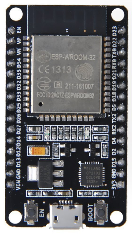
Pin Configuration and Descriptions

The ESP32 NODEMCU board has a variety of pins for different functionalities. Below is a summary of the pin configuration:

Pin Name Function Description
VIN Power Input Input voltage (5V) for powering the board.
3V3 Power Output Regulated 3.3V output for external components.
GND Ground Common ground for the circuit.
EN Enable Enables or disables the chip. Active high.
GPIO0-GPIO39 General Purpose I/O Configurable as digital I/O, ADC, DAC, PWM, I2C, SPI, or UART.
ADC1/ADC2 Analog Input 12-bit ADC channels for analog signal input.
DAC1/DAC2 Digital-to-Analog Converter 8-bit DAC channels for generating analog signals.
TXD0/RXD0 UART Communication Default UART TX and RX pins for serial communication.
SCL/SDA I2C Communication Clock (SCL) and Data (SDA) pins for I2C communication.
MOSI/MISO SPI Communication Master Out Slave In (MOSI) and Master In Slave Out (MISO) for SPI communication.
RST Reset Resets the microcontroller.

Usage Instructions

How to Use the ESP32 in a Circuit

  1. Powering the ESP32:
    • Connect the VIN pin to a 5V power source or use the micro-USB port for power and programming.
    • Ensure the GND pin is connected to the ground of your circuit.
  2. Programming the ESP32:
    • Use the Arduino IDE or ESP-IDF (Espressif IoT Development Framework) for programming.
    • Install the ESP32 board package in the Arduino IDE via the Board Manager.
  3. Connecting Peripherals:
    • Use GPIO pins for digital I/O, ADC pins for analog input, and DAC pins for analog output.
    • For communication, connect I2C, SPI, or UART peripherals to the respective pins.

Important Considerations and Best Practices

  • Voltage Levels: The ESP32 operates at 3.3V logic levels. Avoid connecting 5V signals directly to GPIO pins.
  • Power Supply: Use a stable power source to avoid unexpected resets or malfunctions.
  • Deep Sleep Mode: Utilize deep sleep mode for battery-powered applications to minimize power consumption.
  • Pull-up Resistors: Some GPIO pins require external pull-up resistors for proper operation (e.g., I2C lines).

Example Code for Arduino UNO Integration

Below is an example of using the ESP32 with the Arduino IDE to blink an LED connected to GPIO2:

// Example: Blink an LED connected to GPIO2 on the ESP32

#define LED_PIN 2  // GPIO2 is commonly used for onboard LEDs

void setup() {
  pinMode(LED_PIN, OUTPUT);  // Set GPIO2 as an output pin
}

void loop() {
  digitalWrite(LED_PIN, HIGH);  // Turn the LED on
  delay(1000);                  // Wait for 1 second
  digitalWrite(LED_PIN, LOW);   // Turn the LED off
  delay(1000);                  // Wait for 1 second
}

Troubleshooting and FAQs

Common Issues and Solutions

  1. ESP32 Not Detected by Computer:
    • Ensure the correct USB driver is installed (e.g., CP210x or CH340 driver).
    • Check the USB cable for data transfer capability (some cables are power-only).
  2. Upload Fails in Arduino IDE:
    • Verify the correct board and port are selected in the Arduino IDE.
    • Press and hold the "BOOT" button on the ESP32 while uploading the code.
  3. Wi-Fi Connection Issues:
    • Double-check the SSID and password in your code.
    • Ensure the Wi-Fi network is within range and not using unsupported security protocols.
  4. Random Resets or Instability:
    • Use a stable power supply with sufficient current (at least 500 mA).
    • Avoid using GPIO pins that are reserved for internal functions (e.g., GPIO6-GPIO11).

FAQs

  • Q: Can the ESP32 be powered with 5V?
    A: Yes, the VIN pin or micro-USB port can accept 5V, but the logic level for GPIO pins is 3.3V.

  • Q: How do I use Bluetooth on the ESP32?
    A: Use the Arduino IDE or ESP-IDF to program Bluetooth functionality. The ESP32 supports both Bluetooth Classic and BLE.

  • Q: Can I use the ESP32 with a battery?
    A: Yes, the ESP32 can be powered by a LiPo battery through the VIN pin or a dedicated battery management circuit.

  • Q: What is the maximum range of the ESP32's Wi-Fi?
    A: The range depends on environmental factors but typically extends up to 100 meters in open space.

This documentation provides a comprehensive guide to using the ESP32 NODEMCU for your projects. For further assistance, refer to the official datasheet or community forums.