How to Use wall socket Type I: Examples, Pinouts, and Specs
Introduction
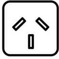
A Wall Socket Type I is an electrical outlet commonly used in Australia, New Zealand, China, and several Pacific Island nations. It features two flat pins arranged in a V-shape and a grounding pin for safety. This socket is designed to handle standard household and commercial electrical loads, making it a reliable choice for powering various appliances and devices.
Explore Projects Built with wall socket Type I
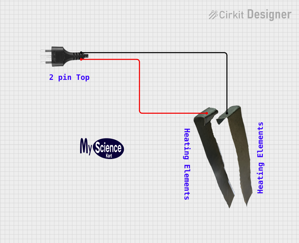


Explore Projects Built with wall socket Type I
Common Applications and Use Cases
- Residential and commercial electrical installations
- Powering household appliances such as refrigerators, microwaves, and televisions
- Industrial equipment requiring Type I plug compatibility
- Use in travel adapters for regions supporting Type I sockets
Technical Specifications
The Wall Socket Type I is designed to meet regional electrical standards and ensure safe operation. Below are the key technical details:
General Specifications
| Parameter | Value |
|---|---|
| Voltage Rating | 220-240V AC |
| Frequency | 50 Hz |
| Maximum Current Rating | 10A or 15A (depending on model) |
| Grounding | Yes (via grounding pin) |
| Pin Configuration | 2 flat pins + 1 grounding pin |
| Material | Flame-retardant plastic, brass contacts |
Pin Configuration and Descriptions
| Pin Name | Description |
|---|---|
| Active (A) | Supplies the live current to the connected device. |
| Neutral (N) | Completes the circuit by returning current to the power source. |
| Ground (G) | Provides a safety path for fault currents to prevent electric shock. |
Usage Instructions
How to Use the Component in a Circuit
Installation:
- Ensure the power supply is turned off before installation.
- Mount the wall socket securely into a standard electrical box.
- Connect the wires to the corresponding terminals:
- Active (A): Connect the live wire (usually brown or red).
- Neutral (N): Connect the neutral wire (usually blue or black).
- Ground (G): Connect the ground wire (usually green or green-yellow).
- Tighten the screws to secure the wires and ensure proper contact.
Testing:
- After installation, turn on the power supply.
- Use a multimeter to verify the voltage between the active and neutral pins (should read ~220-240V).
- Test the grounding pin for continuity to ensure safety.
Usage:
- Plug in a compatible Type I plug to power your device.
- Avoid overloading the socket by ensuring the total current draw does not exceed the rated capacity.
Important Considerations and Best Practices
- Always follow local electrical codes and regulations during installation.
- Use a licensed electrician for installations in residential or commercial settings.
- Avoid using damaged plugs or cords with the socket to prevent electrical hazards.
- Do not exceed the maximum current rating of the socket to avoid overheating or fire risks.
- Regularly inspect the socket for wear, damage, or loose connections.
Troubleshooting and FAQs
Common Issues and Solutions
| Issue | Possible Cause | Solution |
|---|---|---|
| No power to the socket | Loose wiring or tripped circuit breaker | Check wiring and reset the breaker. |
| Device not working when plugged in | Faulty device or plug | Test with another device or plug. |
| Overheating of the socket | Overloaded socket or poor connections | Reduce load and check wiring. |
| Sparks when plugging in a device | Worn-out contacts or loose connections | Replace the socket if necessary. |
FAQs
Can I use a Type I socket in other countries?
- Type I sockets are designed for regions with 220-240V AC power. Using them in other countries may require a voltage converter and plug adapter.
What is the difference between a 10A and 15A Type I socket?
- A 10A socket is suitable for standard household appliances, while a 15A socket is designed for higher-power devices like air conditioners or industrial equipment.
How do I know if the grounding pin is working?
- Use a multimeter to test for continuity between the grounding pin and the electrical panel's ground connection.
Can I install a Type I socket outdoors?
- Yes, but ensure it is installed in a weatherproof enclosure rated for outdoor use.
By following this documentation, you can safely and effectively use a Wall Socket Type I in your electrical installations.