How to Use Heart Pulse Sensor: Examples, Pinouts, and Specs

Introduction
A heart pulse sensor is an electronic device designed to measure the heart rate by detecting the pulsation of blood through the blood vessels. It is a non-invasive sensor that typically uses optical technology to sense the volume changes in microvascular bed of tissue. This sensor is widely used in various applications such as medical monitoring, fitness tracking, and any application where heart rate monitoring is essential.
Explore Projects Built with Heart Pulse Sensor
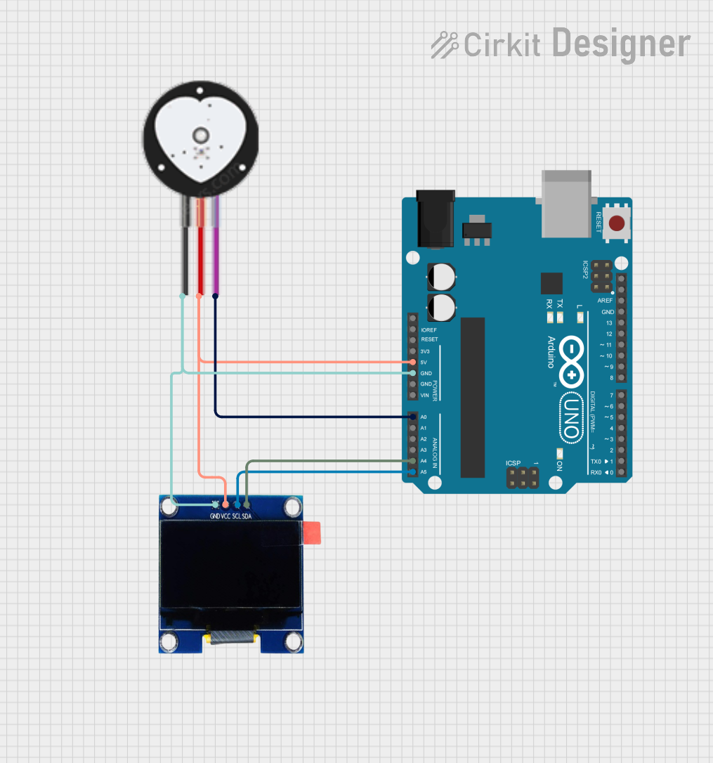
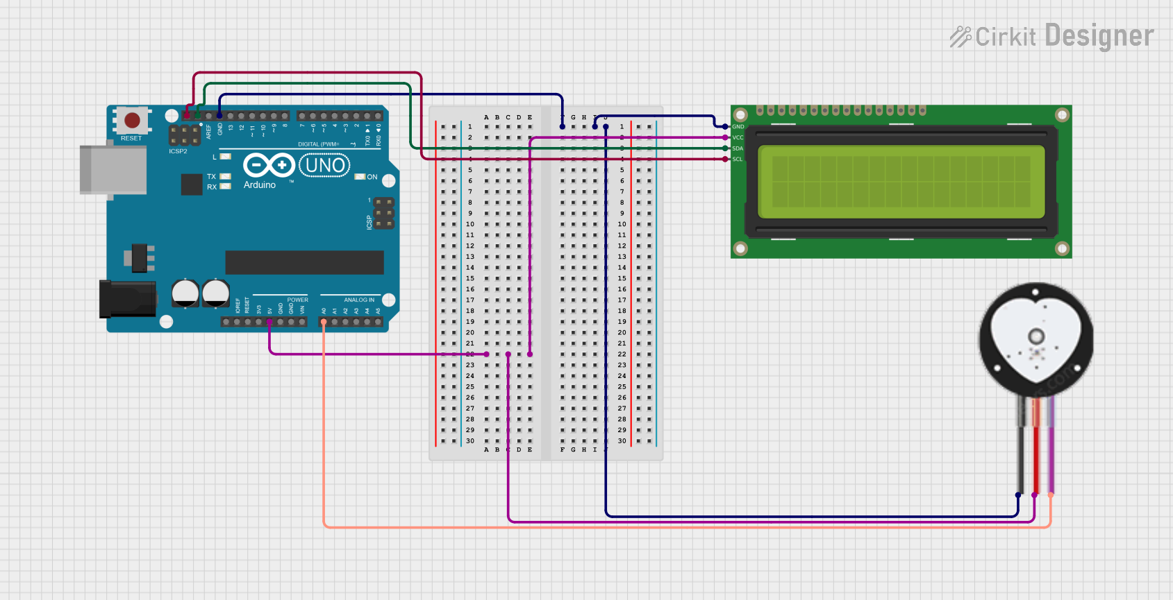
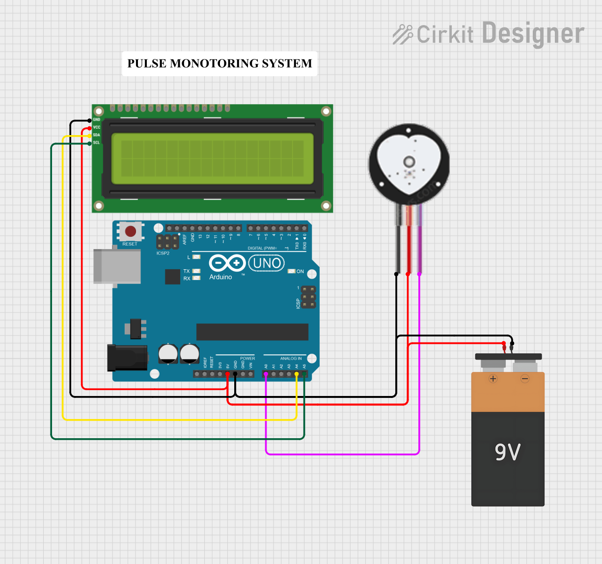
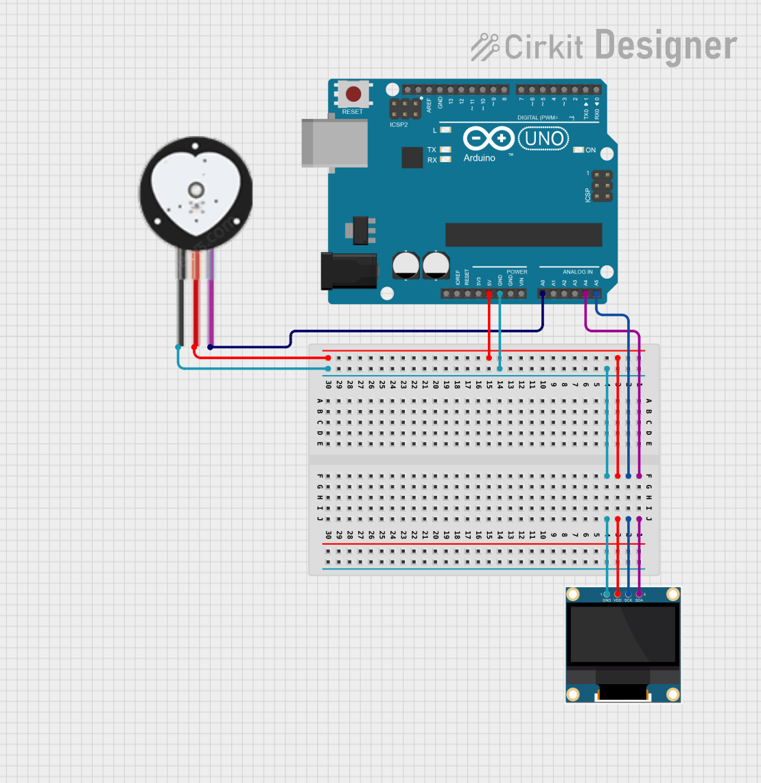
Explore Projects Built with Heart Pulse Sensor
Common Applications and Use Cases
- Fitness Trackers and Smartwatches: To provide real-time heart rate data for athletes and fitness enthusiasts.
- Medical Monitoring Devices: For patient monitoring in hospitals and during physical examinations.
- Biofeedback Devices: To help individuals control their physiological processes.
- Research and Development: In scientific studies related to health and fitness.
Technical Specifications
Key Technical Details
- Operating Voltage: 3.3V to 5V
- Current Consumption: Typically 4mA (max)
- Output Signal Type: Analog voltage
- Peak Wavelength: ~525nm
- Operating Temperature: -40°C to 85°C
Pin Configuration and Descriptions
| Pin Number | Name | Description |
|---|---|---|
| 1 | VCC | Power supply (3.3V to 5V) |
| 2 | GND | Ground connection |
| 3 | SIG | Analog signal output |
Usage Instructions
How to Use the Heart Pulse Sensor in a Circuit
- Power Connection: Connect the VCC pin to a 3.3V or 5V power supply and the GND pin to the ground on your circuit.
- Signal Connection: Connect the SIG pin to an analog input on your microcontroller, such as an Arduino UNO.
- Mounting: Secure the sensor to the fingertip or earlobe for consistent readings.
- Reading Data: Use the microcontroller's ADC to read the analog signal and process it to determine the heart rate.
Important Considerations and Best Practices
- Stable Placement: Ensure the sensor is placed firmly without too much pressure to avoid inaccurate readings.
- Ambient Light: Minimize exposure to ambient light as it can interfere with the sensor's readings.
- Warm-Up Time: Allow the sensor to warm up for a few seconds to stabilize before taking measurements.
- Signal Smoothing: Implement software filtering to smooth out the signal for more accurate heart rate calculation.
Example Code for Arduino UNO
// Define the analog pin connected to the heart pulse sensor
const int pulsePin = A0;

void setup() {
  // Begin serial communication at a baud rate of 9600
  Serial.begin(9600);
}

void loop() {
  // Read the analog value from the pulse sensor
  int pulseValue = analogRead(pulsePin);

  // Convert the analog value to a voltage
  float voltage = pulseValue * (5.0 / 1023.0);

  // Print the voltage to the Serial Monitor
  Serial.println(voltage);

  // Wait for a short period before reading again
  delay(200);
}
Troubleshooting and FAQs
Common Issues Users Might Face
- Inconsistent Readings: If the sensor is not properly secured or there is movement, the readings may fluctuate.
- No Signal: Ensure that the sensor is correctly powered and that the pins are connected properly.
- Ambient Light Interference: Shield the sensor from direct light sources.
Solutions and Tips for Troubleshooting
- Secure Placement: Use a band or clip to hold the sensor in place without applying too much pressure.
- Check Connections: Verify that all connections are secure and that the correct pins are used.
- Calibration: Calibrate the sensor by comparing its readings with a known good heart rate monitor.
FAQs
Q: Can the heart pulse sensor be used during intense physical activity? A: Yes, but ensure it is securely attached to avoid motion artifacts in the readings.
Q: How accurate is the heart pulse sensor? A: The accuracy can vary based on several factors, including placement and individual physiology. It is generally suitable for fitness and hobbyist applications but may not be precise enough for medical diagnosis.
Q: Is it possible to use the heart pulse sensor with a battery? A: Yes, as long as the battery provides a stable voltage within the sensor's operating range (3.3V to 5V).