
How to Use TRIMPOT: Examples, Pinouts, and Specs

 Design with TRIMPOT in Cirkit Designer
Introduction
A trimmer potentiometer, commonly referred to as a trimpot, is a small adjustable resistor used to calibrate or fine-tune electronic circuits. It typically features three terminals and allows for manual adjustment of resistance by rotating a screw or knob. Trimpots are widely used in applications where precise resistance tuning is required, such as in voltage dividers, sensor calibration, and amplifier gain adjustments.
Explore Projects Built with TRIMPOT
 Open Project in Cirkit Designer
 Open Project in Cirkit Designer
 Open Project in Cirkit Designer
 Open Project in Cirkit Designer
Explore Projects Built with TRIMPOT
Open Project in Cirkit DesignerOpen Project in Cirkit DesignerOpen Project in Cirkit DesignerOpen Project in Cirkit DesignerCommon Applications
- Calibration of sensor circuits
- Fine-tuning voltage or current in power supplies
- Adjusting the gain of operational amplifiers
- Setting reference voltages in analog circuits
- Balancing bridge circuits
Technical Specifications
Below are the general technical specifications for a typical trimpot. Note that specific values may vary depending on the model and manufacturer.
| Parameter | Specification |
|---|---|
| Resistance Range | 100 Ω to 1 MΩ (varies by model) |
| Tolerance | ±10% to ±20% |
| Power Rating | 0.1 W to 0.5 W |
| Adjustment Type | Single-turn or multi-turn |
| Operating Temperature | -55°C to +125°C |
| Mounting Type | Through-hole or surface-mount |
Pin Configuration
Trimpots typically have three terminals, as described below:
| Pin | Description |
|---|---|
| Pin 1 | One end of the resistive track |
| Pin 2 | Wiper (adjustable terminal for variable resistance) |
| Pin 3 | The other end of the resistive track |
Usage Instructions
How to Use a Trimpot in a Circuit
- Identify the Pins: Locate the three pins of the trimpot. Pin 1 and Pin 3 are connected to the ends of the resistive track, while Pin 2 is the wiper.
- Connect the Circuit:
- For variable resistance: Connect Pin 1 and Pin 2 to your circuit. The resistance between these pins will vary as you adjust the trimpot.
- For voltage division: Connect Pin 1 to the input voltage, Pin 3 to ground, and Pin 2 to the output. The output voltage will vary based on the wiper position.
- Adjust the Resistance: Use a small screwdriver to rotate the adjustment screw or knob. Turning it clockwise or counterclockwise will increase or decrease the resistance, respectively.
Important Considerations
- Power Rating: Ensure the trimpot's power rating is not exceeded to avoid damage.
- Mechanical Stress: Avoid applying excessive force when adjusting the screw to prevent mechanical failure.
- Stability: For applications requiring high stability, use multi-turn trimpots for finer adjustments.
- Mounting: Choose the appropriate mounting type (through-hole or surface-mount) based on your PCB design.
Example: Using a Trimpot with Arduino UNO
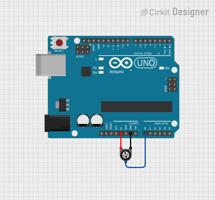
Below is an example of using a 10 kΩ trimpot to create a voltage divider and read the output voltage with an Arduino UNO.
// Example: Reading a trimpot value with Arduino UNO
// Connect Pin 1 of the trimpot to 5V, Pin 3 to GND, and Pin 2 to A0.

const int potPin = A0; // Analog pin connected to the trimpot wiper (Pin 2)
int potValue = 0;      // Variable to store the analog reading

void setup() {
  Serial.begin(9600); // Initialize serial communication at 9600 baud
}

void loop() {
  potValue = analogRead(potPin); // Read the analog value (0-1023)
  float voltage = potValue * (5.0 / 1023.0); // Convert to voltage (0-5V)

  // Print the value and voltage to the Serial Monitor
  Serial.print("Analog Value: ");
  Serial.print(potValue);
  Serial.print(" | Voltage: ");
  Serial.println(voltage);

  delay(500); // Wait for 500ms before the next reading
}
Troubleshooting and FAQs
Common Issues
No Change in Resistance:
- Cause: The trimpot may be damaged or improperly connected.
- Solution: Verify the connections and check the trimpot with a multimeter.
Output Voltage Not Varying:
- Cause: Incorrect wiring or a faulty trimpot.
- Solution: Ensure Pin 1 is connected to the input voltage, Pin 3 to ground, and Pin 2 to the output.
Trimpot Overheating:
- Cause: Exceeding the power rating.
- Solution: Use a trimpot with a higher power rating or reduce the current in the circuit.
FAQs
Q: Can I use a trimpot as a permanent resistor in a circuit?
A: While trimpots are designed for calibration and adjustment, they can be used as permanent resistors. However, they are less stable and durable than fixed resistors for long-term use.
Q: What is the difference between single-turn and multi-turn trimpots?
A: Single-turn trimpots allow for quick adjustments but offer less precision. Multi-turn trimpots provide finer control over resistance adjustments, making them ideal for applications requiring high accuracy.
Q: How do I measure the resistance of a trimpot?
A: Use a multimeter to measure the resistance between Pin 1 and Pin 3 for the total resistance. To measure the variable resistance, measure between Pin 1 and Pin 2 or Pin 2 and Pin 3 while adjusting the wiper.