How to Use BreadBoard: Examples, Pinouts, and Specs

Introduction
A breadboard is a construction base for prototyping electronics. It allows for the creation of temporary circuits without soldering, using a grid of interconnected holes to insert components and wires. Breadboards are essential tools for both beginners and experienced electronics enthusiasts, enabling quick and easy experimentation with circuit designs.
Explore Projects Built with BreadBoard
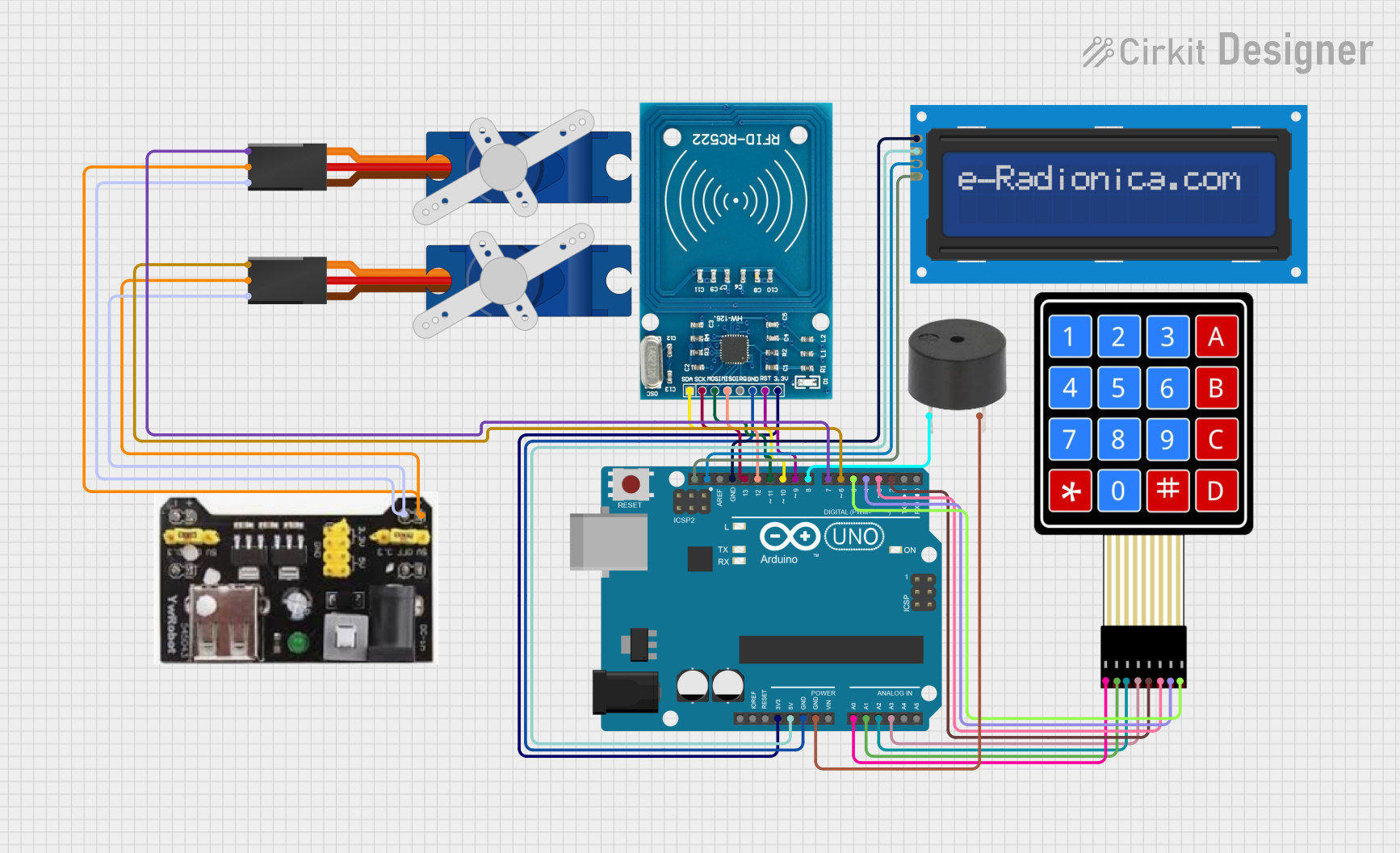
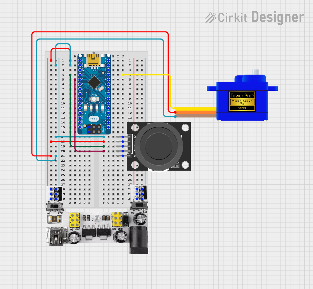
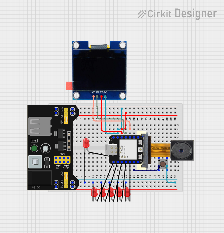
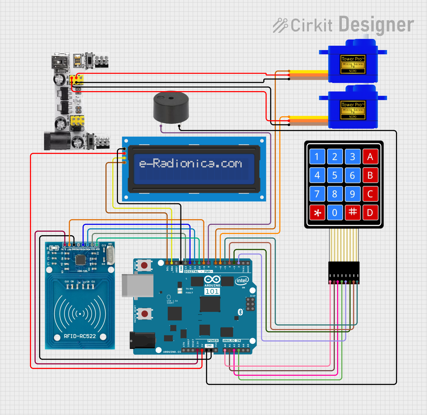
Explore Projects Built with BreadBoard
Common Applications and Use Cases
- Prototyping: Quickly test and modify circuit designs without permanent soldering.
- Educational Purposes: Ideal for learning and teaching electronics concepts.
- Testing Components: Easily test individual components like resistors, capacitors, and ICs.
- DIY Projects: Create and iterate on personal electronics projects.
Technical Specifications
Key Technical Details
| Specification | Description |
|---|---|
| Material | ABS plastic |
| Dimensions | Typically 830 tie-points (e.g., 6.5 x 2.1 inches) |
| Power Rails | Dual power rails (positive and negative) |
| Tie-Points | 830 (e.g., 630 in main area, 200 in power rails) |
| Connectivity | Spring clips for secure component placement |
| Voltage Rating | Up to 12V DC |
| Current Rating | Up to 1A |
Pin Configuration and Descriptions
Breadboards do not have traditional pins like ICs, but they have a specific layout that is important to understand:
| Section | Description |
|---|---|
| Power Rails | Two rows on each side for distributing power (usually marked with + and -) |
| Terminal Strips | Main area with interconnected rows of 5 holes each, used for placing components |
| Bus Strips | Vertical columns that connect the power rails to the terminal strips |
Usage Instructions
How to Use the Breadboard in a Circuit
Power Distribution:
- Connect the power supply to the power rails. Typically, the red rail is for positive voltage, and the blue/black rail is for ground.
Component Placement:
- Insert components into the terminal strips. Ensure that each leg of the component is in a separate row to avoid short circuits.
Interconnections:
- Use jumper wires to connect different components. Insert one end of the wire into the same row as the component leg and the other end into the desired connection point.
Important Considerations and Best Practices
- Avoid Overloading: Do not exceed the voltage and current ratings to prevent damage.
- Check Connections: Ensure all connections are secure and components are properly seated.
- Use Color-Coded Wires: Helps in identifying connections and troubleshooting.
- Keep it Organized: Neat wiring reduces the risk of short circuits and makes debugging easier.
Troubleshooting and FAQs
Common Issues Users Might Face
Loose Connections:
- Solution: Ensure all components and wires are firmly inserted into the breadboard.
Short Circuits:
- Solution: Double-check that no two components are unintentionally connected. Use a multimeter to identify shorts.
Component Damage:
- Solution: Verify that the voltage and current ratings are not exceeded. Replace damaged components.
Power Issues:
- Solution: Ensure the power supply is correctly connected to the power rails and that the power source is functioning.
FAQs
Q1: Can I use a breadboard for high-frequency circuits?
- A1: Breadboards are not ideal for high-frequency circuits due to parasitic capacitance and inductance. For such applications, consider using a PCB.
Q2: How do I connect an Arduino UNO to a breadboard?
- A2: Use jumper wires to connect the Arduino's pins to the breadboard. For example, connect the 5V and GND pins of the Arduino to the power rails of the breadboard.
Q3: Can I reuse a breadboard?
- A3: Yes, breadboards are designed for multiple uses. Simply remove the components and wires, and you can start a new project.
Example Code for Arduino UNO
Here is a simple example of connecting an LED to an Arduino UNO using a breadboard:
// Define the pin for the LED
const int ledPin = 13;

void setup() {
  // Initialize the digital pin as an output
  pinMode(ledPin, OUTPUT);
}

void loop() {
  // Turn the LED on (HIGH is the voltage level)
  digitalWrite(ledPin, HIGH);
  delay(1000); // Wait for a second

  // Turn the LED off by making the voltage LOW
  digitalWrite(ledPin, LOW);
  delay(1000); // Wait for a second
}
Connections:
- Connect the LED's anode (long leg) to pin 13 on the Arduino.
- Connect the LED's cathode (short leg) to a 220-ohm resistor.
- Connect the other end of the resistor to the GND rail on the breadboard.
- Connect the GND rail to the GND pin on the Arduino.
By following this documentation, users can effectively utilize a breadboard for various electronics projects, ensuring proper setup and troubleshooting techniques.