Cirkit Designer Logo
Cirkit Designer
Your all-in-one circuit design IDE
Home / 
Component Documentation

How to Use BME/BMP280: Examples, Pinouts, and Specs

Image of BME/BMP280
Cirkit Designer LogoDesign with BME/BMP280 in Cirkit Designer

Introduction

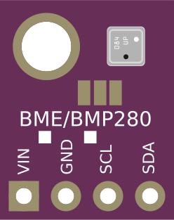
The BME/BMP280 sensor is a precision sensor from Bosch that is designed to measure barometric pressure, temperature, and in the case of the BME280, humidity. These sensors are widely used in environmental monitoring, weather stations, indoor navigation, fitness trackers, and various IoT applications due to their small form factor, low power consumption, and excellent accuracy.

Explore Projects Built with BME/BMP280

Use Cirkit Designer to design, explore, and prototype these projects online. Some projects support real-time simulation. Click "Open Project" to start designing instantly!
ESP32-Based Environmental Monitoring System with Solar Charging
Image of IoT Ola (Final): A project utilizing BME/BMP280 in a practical application
This circuit features an ESP32 microcontroller interfaced with a BME/BMP280 sensor for environmental monitoring and an MH-Z19B sensor for CO2 measurement, both communicating via I2C (SCL, SDA) and serial (TX, RX) connections respectively. It includes a SIM800L module for GSM communication, connected to the ESP32 via serial (TXD, RXD). Power management is handled by two TP4056 modules for charging 18650 Li-ion batteries via solar panels, with a step-up boost converter to provide consistent voltage to the MH-Z19B, and voltage regulation for the SIM800L. Decoupling capacitors are used to stabilize the power supply to the BME/BMP280 and ESP32.
Cirkit Designer LogoOpen Project in Cirkit Designer
ESP32-Based Environmental Sensing Station with Wi-Fi and Light Intensity Measurement
Image of multi esp32: A project utilizing BME/BMP280 in a practical application
This circuit is designed to collect environmental data and light intensity measurements using the ESP32 microcontroller, which communicates with a BME/BMP280 sensor and a BH1750 sensor via I2C, and transmits the data through an LD2410C communication module using serial communication.
Cirkit Designer LogoOpen Project in Cirkit Designer
ESP32-Controlled Environmental Monitoring and Fan Regulation System
Image of PWM STandard ESP32WROOM (tested): A project utilizing BME/BMP280 in a practical application
This circuit features an ESP32 microcontroller interfaced with a BME/BMP280 sensor for environmental monitoring, controlling a 12V PWM fan via a relay module. The ESP32 uses I2C communication (SCL, SDA) to read data from the BME/BMP280 sensor and controls the fan speed and on/off state through GPIO pins connected to the relay and the fan's PWM input. A USB regulator provides power to the circuit, and the DC power source is used to drive the relay and the fan.
Cirkit Designer LogoOpen Project in Cirkit Designer
Arduino UNO with Dual BME/BMP280 Sensors for Environmental Monitoring
Image of Instrumentation: A project utilizing BME/BMP280 in a practical application
This circuit consists of an Arduino UNO microcontroller connected to a BME/BMP280 sensor. The Arduino provides power to the sensor and communicates with it via I2C, using its A4 and A5 pins as SDA and SCL lines, respectively. The purpose of this circuit is likely to read environmental data such as temperature, pressure, and humidity from the BME/BMP280 sensor.
Cirkit Designer LogoOpen Project in Cirkit Designer

Explore Projects Built with BME/BMP280

Use Cirkit Designer to design, explore, and prototype these projects online. Some projects support real-time simulation. Click "Open Project" to start designing instantly!
Image of IoT Ola (Final): A project utilizing BME/BMP280 in a practical application
ESP32-Based Environmental Monitoring System with Solar Charging
This circuit features an ESP32 microcontroller interfaced with a BME/BMP280 sensor for environmental monitoring and an MH-Z19B sensor for CO2 measurement, both communicating via I2C (SCL, SDA) and serial (TX, RX) connections respectively. It includes a SIM800L module for GSM communication, connected to the ESP32 via serial (TXD, RXD). Power management is handled by two TP4056 modules for charging 18650 Li-ion batteries via solar panels, with a step-up boost converter to provide consistent voltage to the MH-Z19B, and voltage regulation for the SIM800L. Decoupling capacitors are used to stabilize the power supply to the BME/BMP280 and ESP32.
Cirkit Designer LogoOpen Project in Cirkit Designer
Image of multi esp32: A project utilizing BME/BMP280 in a practical application
ESP32-Based Environmental Sensing Station with Wi-Fi and Light Intensity Measurement
This circuit is designed to collect environmental data and light intensity measurements using the ESP32 microcontroller, which communicates with a BME/BMP280 sensor and a BH1750 sensor via I2C, and transmits the data through an LD2410C communication module using serial communication.
Cirkit Designer LogoOpen Project in Cirkit Designer
Image of PWM STandard ESP32WROOM (tested): A project utilizing BME/BMP280 in a practical application
ESP32-Controlled Environmental Monitoring and Fan Regulation System
This circuit features an ESP32 microcontroller interfaced with a BME/BMP280 sensor for environmental monitoring, controlling a 12V PWM fan via a relay module. The ESP32 uses I2C communication (SCL, SDA) to read data from the BME/BMP280 sensor and controls the fan speed and on/off state through GPIO pins connected to the relay and the fan's PWM input. A USB regulator provides power to the circuit, and the DC power source is used to drive the relay and the fan.
Cirkit Designer LogoOpen Project in Cirkit Designer
Image of Instrumentation: A project utilizing BME/BMP280 in a practical application
Arduino UNO with Dual BME/BMP280 Sensors for Environmental Monitoring
This circuit consists of an Arduino UNO microcontroller connected to a BME/BMP280 sensor. The Arduino provides power to the sensor and communicates with it via I2C, using its A4 and A5 pins as SDA and SCL lines, respectively. The purpose of this circuit is likely to read environmental data such as temperature, pressure, and humidity from the BME/BMP280 sensor.
Cirkit Designer LogoOpen Project in Cirkit Designer

Technical Specifications

Key Technical Details

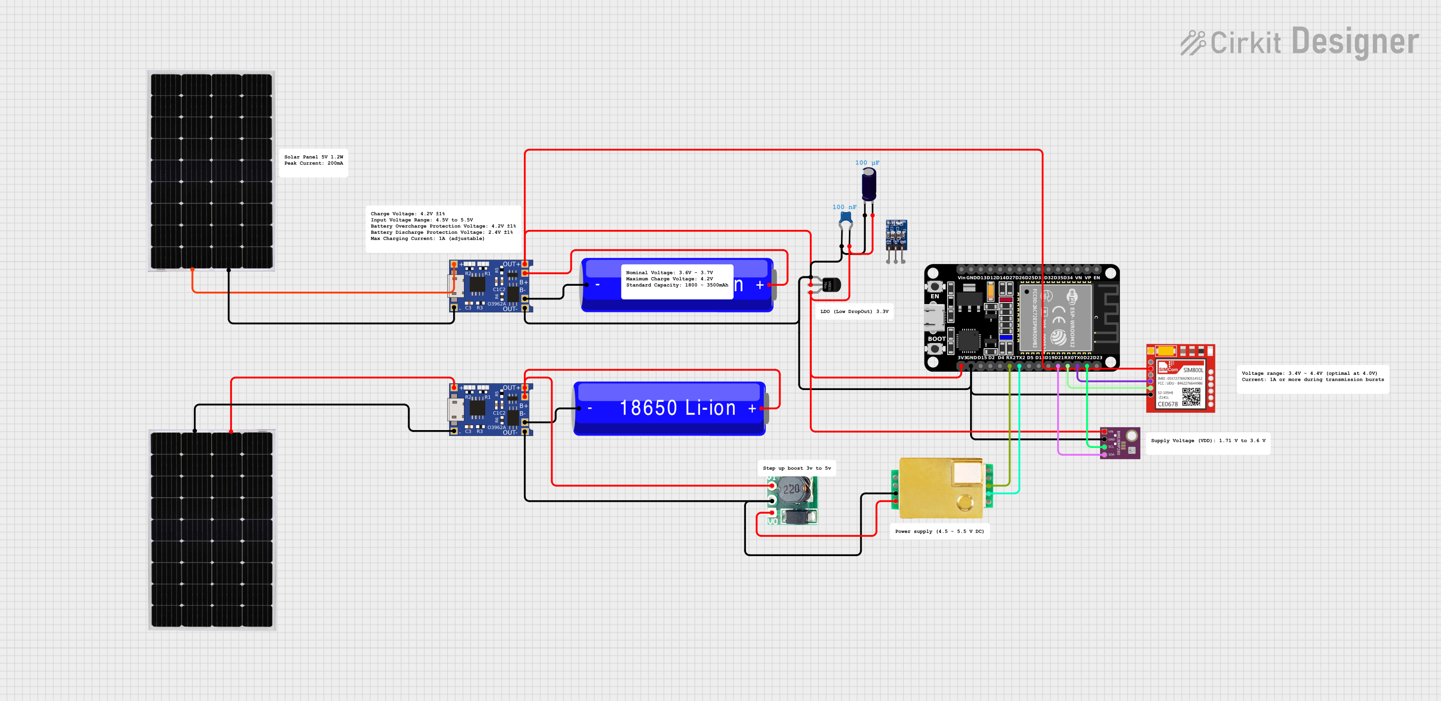
  • Supply Voltage (VDD): 1.71 V to 3.6 V
  • Interface: I²C (up to 3.4 MHz) and SPI (up to 10 MHz)
  • Operating Range (Pressure): 300 hPa to 1100 hPa (equivalent to +9000m to -500m above/below sea level)
  • Operating Range (Temperature): -40°C to +85°C
  • Relative Humidity (BME280 only): 0% to 100%
  • Accuracy (Temperature): ±1.0°C
  • Accuracy (Pressure): ±1 hPa (or ±0.12m)
  • Accuracy (Humidity, BME280 only): ±3% relative humidity

Pin Configuration and Descriptions

Pin Number Name Description
1 VDD Power supply voltage
2 GND Ground
3 SDO Serial Data Out for SPI, MSB for I²C address
4 SDI Serial Data In for SPI, I²C data
5 SCK Serial Clock for SPI, I²C clock
6 CSB Chip Select for SPI, active low
7 SDO Serial Data Out for SPI, LSB for I²C address
8 VDDIO Interface voltage

Usage Instructions

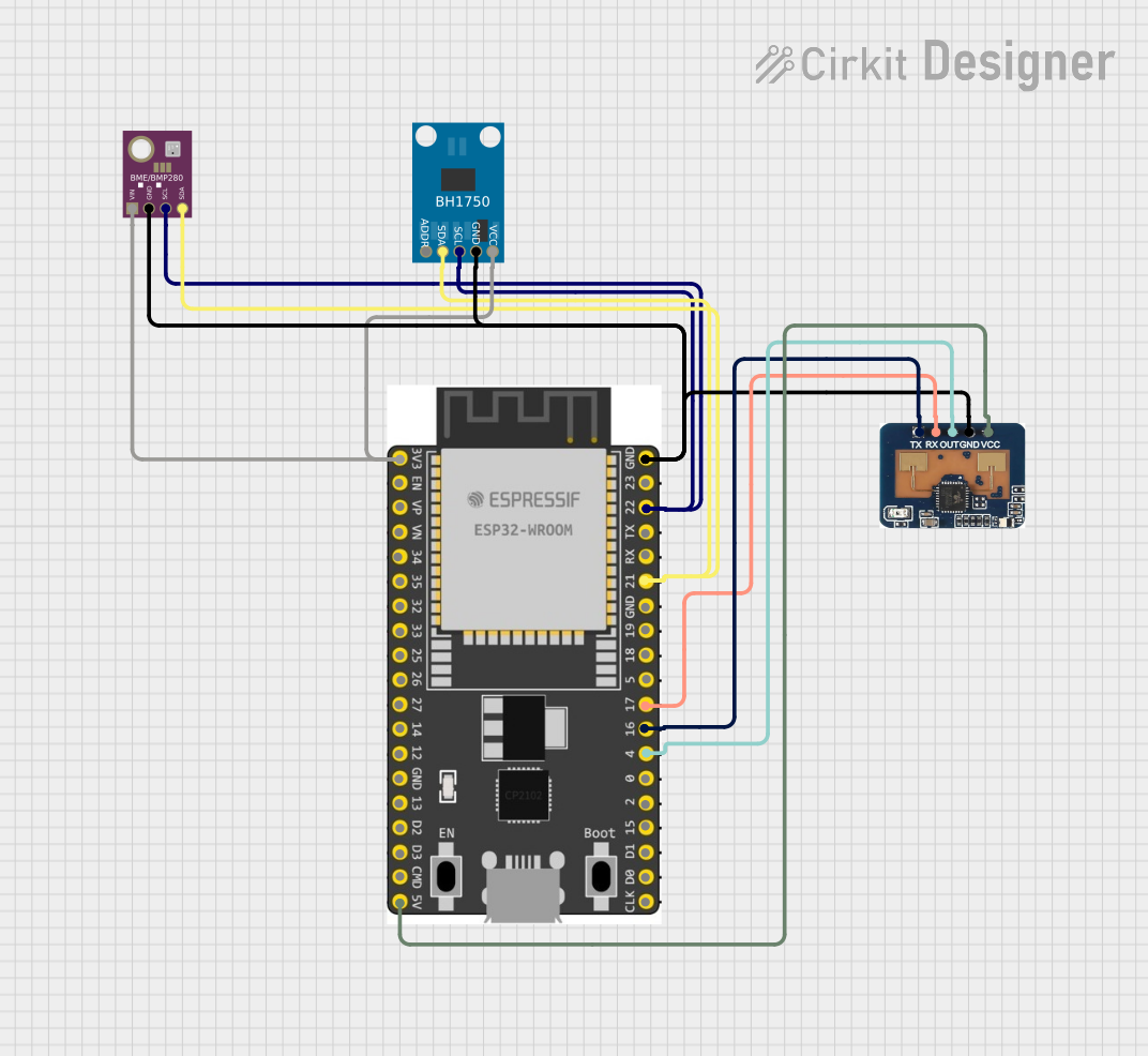
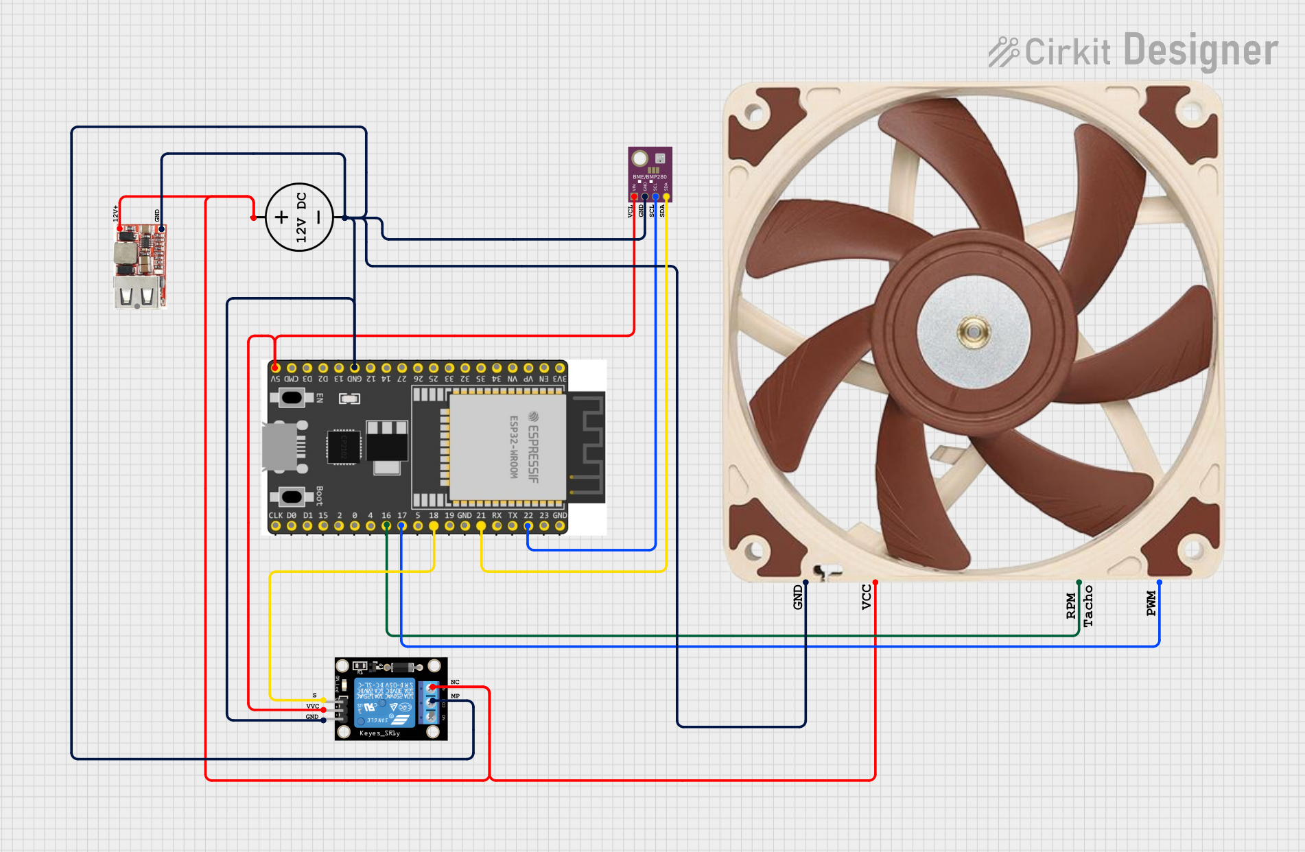
Integration with a Circuit

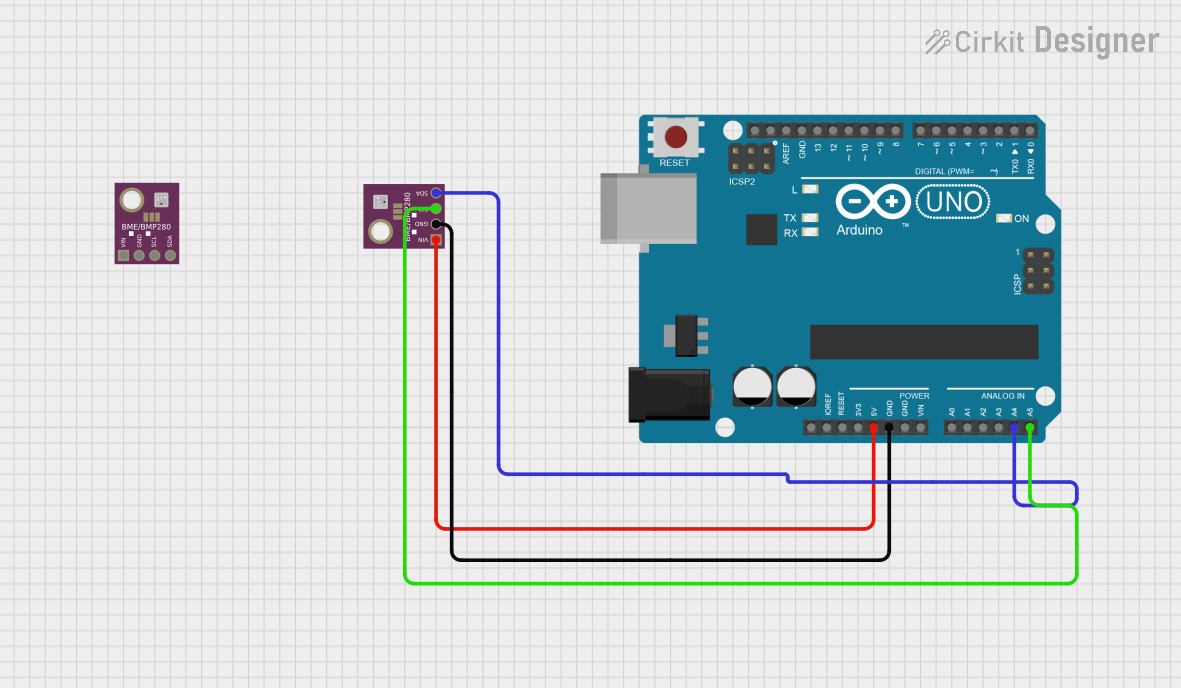
To use the BME/BMP280 sensor in a circuit:

  1. Connect the VDD pin to a power supply within the specified range (1.71 V to 3.6 V).
  2. Connect the GND pin to the ground of the power supply.
  3. For I²C communication, connect the SDI (SDA) and SCK (SCL) pins to the corresponding I²C data and clock lines.
  4. For SPI communication, connect the SDI, SDO, SCK, and CSB pins to the corresponding SPI lines.
  5. Optionally, connect the VDDIO pin if a different IO voltage level is required for the interface.

Best Practices

  • Use pull-up resistors on the I²C data and clock lines.
  • Keep the power supply stable and free of noise.
  • Place the sensor away from heat sources to avoid false temperature readings.
  • Use proper decoupling capacitors close to the sensor's power supply pins to minimize power supply ripple.

Example Code for Arduino UNO

Below is an example of how to read data from the BME/BMP280 sensor using an Arduino UNO with the I²C interface.

#include <Wire.h>
#include <Adafruit_Sensor.h>
#include <Adafruit_BME280.h>

Adafruit_BME280 bme; // I2C

void setup() {
  Serial.begin(9600);
  if (!bme.begin(0x76)) {   // Address 0x76 or 0x77 (SDO pin low or high)
    Serial.println("Could not find a valid BME280 sensor, check wiring!");
    while (1);
  }
}

void loop() {
  Serial.print("Temperature = ");
  Serial.print(bme.readTemperature());
  Serial.println(" *C");

  Serial.print("Pressure = ");
  Serial.print(bme.readPressure() / 100.0F);
  Serial.println(" hPa");

  Serial.print("Humidity = ");
  Serial.print(bme.readHumidity());
  Serial.println(" %");

  delay(2000); // Wait for 2 seconds between measurements
}

Ensure that the BME/BMP280 library is installed in the Arduino IDE before uploading this code to the Arduino UNO.

Troubleshooting and FAQs

Common Issues

  • Sensor not detected: Check the wiring, ensure that the sensor is powered, and that the I²C address is correct.
  • Inaccurate readings: Verify that the sensor is not placed near heat sources or that it's not being affected by the heat generated by other components.
  • No humidity data: Remember that the BMP280 does not measure humidity; only the BME280 does.

Solutions and Tips

  • Wiring issues: Double-check connections and use a multimeter to ensure continuity.
  • Power supply: Ensure that the power supply is within the specified range and stable.
  • Pull-up resistors: If using I²C, make sure pull-up resistors are connected to the SDA and SCL lines.

FAQs

Q: Can I use multiple BME/BMP280 sensors on the same I²C bus? A: Yes, you can use two sensors on the same I²C bus by using different I²C addresses (0x76 and 0x77).

Q: How can I calibrate the sensor? A: The BME/BMP280 sensors are factory-calibrated, but for critical applications, you can perform additional calibration using known reference values.

Q: What is the power consumption of the sensor? A: The BME/BMP280 sensors have very low power consumption, typically less than 1 µA in sleep mode.

For further assistance, consult the manufacturer's datasheet and application notes.