How to Use CB Connector 10 pin (female): Examples, Pinouts, and Specs
Introduction
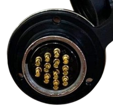
The CB Connector 12 Pin (Female) is a versatile and reliable connector designed for use in electronic circuits. It features 12 female pins that provide a secure interface for signal and power transmission. This connector is commonly used in applications requiring multi-pin connections, such as microcontroller projects, industrial equipment, and communication systems. Its robust design ensures durability and consistent performance in a variety of environments.
Explore Projects Built with CB Connector 10 pin (female)


Explore Projects Built with CB Connector 10 pin (female)
Common Applications and Use Cases
- Microcontroller and development board connections
- Signal and power distribution in electronic circuits
- Industrial automation and control systems
- Communication devices and modules
- Prototyping and testing of electronic designs
Technical Specifications
Below are the key technical details and pin configuration for the CB Connector 12 Pin (Female):
Key Technical Details
| Parameter | Specification |
|---|---|
| Manufacturer | [Insert Manufacturer Name] |
| Manufacturer Part ID | [Insert Manufacturer Part ID] |
| Number of Pins | 12 |
| Connector Type | Female |
| Contact Material | Copper alloy (plated for durability) |
| Insulation Material | Thermoplastic (high-temperature rated) |
| Current Rating | Up to 3A per pin |
| Voltage Rating | Up to 250V AC/DC |
| Operating Temperature | -40°C to +85°C |
| Mounting Style | Through-hole or panel mount |
| Durability | 500 mating cycles |
Pin Configuration and Descriptions
The CB Connector 12 Pin (Female) has 12 pins arranged in a single or dual row, depending on the specific model. Below is a general description of the pin layout:
| Pin Number | Description |
|---|---|
| 1 | Signal/Power Line 1 |
| 2 | Signal/Power Line 2 |
| 3 | Signal/Power Line 3 |
| 4 | Signal/Power Line 4 |
| 5 | Signal/Power Line 5 |
| 6 | Signal/Power Line 6 |
| 7 | Signal/Power Line 7 |
| 8 | Signal/Power Line 8 |
| 9 | Signal/Power Line 9 |
| 10 | Signal/Power Line 10 |
| 11 | Signal/Power Line 11 |
| 12 | Signal/Power Line 12 |
Note: The specific pin assignments may vary depending on the application. Always refer to the circuit design or schematic for proper pin usage.
Usage Instructions
How to Use the CB Connector 12 Pin (Female) in a Circuit
Mounting the Connector:
- If using a through-hole version, solder the connector onto the PCB using appropriate soldering techniques.
- For panel-mount versions, secure the connector to the panel using screws or clips.
Wiring:
- Connect wires or cables to the corresponding male connector or solder directly to the pins.
- Ensure proper alignment of the male and female connectors to avoid damage.
Integration with Microcontrollers:
- The CB Connector 12 Pin (Female) can be used to interface with microcontrollers like the Arduino UNO.
- Assign each pin to a specific signal or power line as per your circuit design.
Important Considerations and Best Practices
- Pin Alignment: Always ensure proper alignment when mating the connector with its counterpart to prevent bent or damaged pins.
- Current and Voltage Ratings: Do not exceed the specified current and voltage ratings to avoid overheating or failure.
- Environmental Conditions: Use the connector within the specified operating temperature range for optimal performance.
- Secure Connections: For critical applications, use locking mechanisms or strain relief to prevent accidental disconnection.
Example: Connecting to an Arduino UNO
Below is an example of how to use the CB Connector 12 Pin (Female) to connect an Arduino UNO to external components:
// Example: Using CB Connector 12 Pin (Female) with Arduino UNO
// This example demonstrates how to read a signal from Pin 1 and control an LED on Pin 2.

const int inputPin = 2;  // Pin 1 of the connector is connected to Arduino Pin 2
const int ledPin = 3;    // Pin 2 of the connector is connected to Arduino Pin 3

void setup() {
  pinMode(inputPin, INPUT);  // Set inputPin as input
  pinMode(ledPin, OUTPUT);   // Set ledPin as output
}

void loop() {
  int signal = digitalRead(inputPin);  // Read signal from inputPin
  if (signal == HIGH) {
    digitalWrite(ledPin, HIGH);  // Turn on LED if signal is HIGH
  } else {
    digitalWrite(ledPin, LOW);   // Turn off LED if signal is LOW
  }
}
Note: Ensure proper wiring between the CB Connector and the Arduino UNO. Use resistors if necessary to limit current.
Troubleshooting and FAQs
Common Issues and Solutions
Loose Connections:
- Issue: The connector feels loose or disconnects easily.
- Solution: Check for proper mating with the male connector. Use locking mechanisms if available.
Bent or Damaged Pins:
- Issue: Pins are bent or broken, causing poor contact.
- Solution: Carefully straighten bent pins using needle-nose pliers. Replace the connector if pins are damaged.
Signal Interference:
- Issue: Noise or interference in the signal lines.
- Solution: Use shielded cables and ensure proper grounding.
Overheating:
- Issue: The connector becomes hot during operation.
- Solution: Verify that the current and voltage ratings are not being exceeded.
FAQs
Q1: Can this connector handle both power and signal lines?
A1: Yes, the CB Connector 12 Pin (Female) is designed to handle both power and signal lines, provided the current and voltage ratings are not exceeded.
Q2: Is this connector compatible with other 12-pin connectors?
A2: The connector is compatible with standard 12-pin male connectors, but always verify the pin layout and specifications.
Q3: Can I use this connector in outdoor applications?
A3: The connector is not inherently weatherproof. For outdoor use, consider additional sealing or use a weatherproof version.
Q4: How many mating cycles can this connector withstand?
A4: The connector is rated for up to 500 mating cycles under normal operating conditions.