How to Use ESP32 38 PINS: Examples, Pinouts, and Specs
Introduction
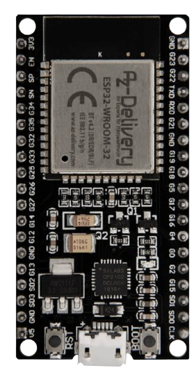
The ESP32 is a versatile and powerful microcontroller with integrated Wi-Fi and Bluetooth capabilities, designed for a wide range of applications from low-power sensor networks to more demanding tasks such as voice encoding, music streaming, and MP3 decoding. The '38 PINS' variant provides ample GPIO (General Purpose Input/Output) pins for interfacing with various peripherals and sensors. Common applications include smart home devices, wearable electronics, Internet of Things (IoT) devices, and complex automation systems.
Explore Projects Built with ESP32 38 PINS


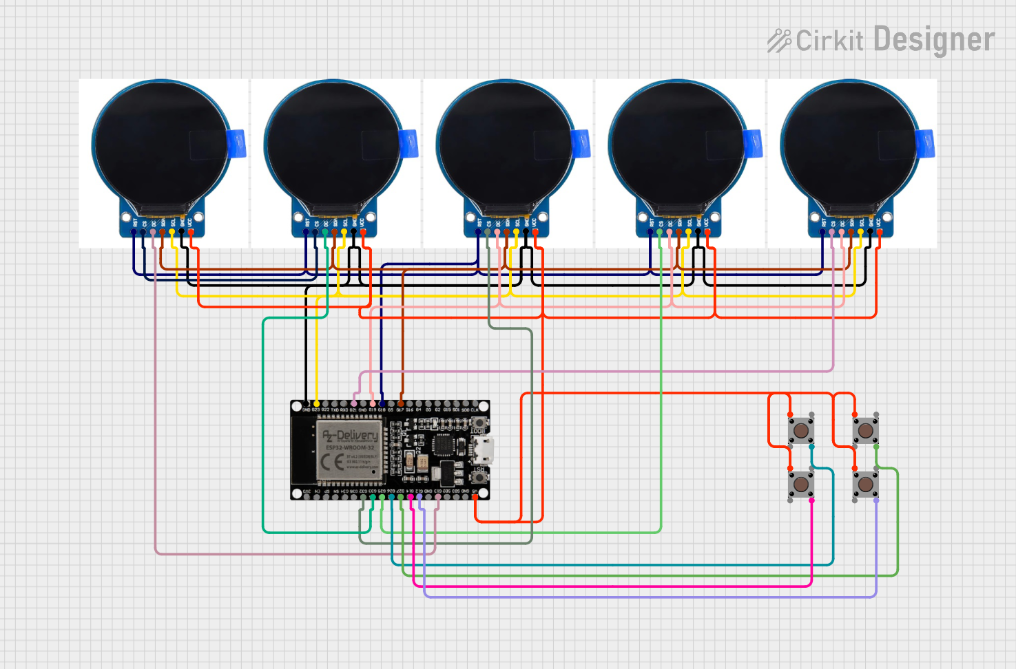

Explore Projects Built with ESP32 38 PINS
Technical Specifications
Key Technical Details
- Microcontroller: Tensilica Xtensa® Dual-Core 32-bit LX6 microprocessor
- Operating Voltage: 3.3V
- Input Voltage (recommended): 7-12V
- Input Voltage (limit): 6-20V
- Digital I/O Pins: 34 (of which 12 can be configured as PWM outputs)
- Analog Input Pins: 18 (ADC channels, up to 12-bit resolution)
- Analog Output Pins: 2 (DAC channels, 8-bit resolution)
- Wi-Fi: 802.11 b/g/n (up to 150 Mbps), WPA/WPA2 Personal and Enterprise
- Bluetooth: v4.2 BR/EDR and BLE standards
- Flash Memory: Up to 16 MB
- SRAM: 520 KB
- Clock Speed: Up to 240 MHz
- Interfaces: I2C, SPI, UART, CAN, IR, PWM, DAC, ADC
- Temperature Range: -40°C to +125°C
Pin Configuration and Descriptions
| Pin Number | Function | Description |
|---|---|---|
| 1-2 | GND | Ground |
| 3 | 3V3 | 3.3V power supply |
| 4-5 | EN | Chip enable, active high |
| 6-7 | VP, VN | Sensor VP and VN pins, ADC0 and ADC1 |
| 8-21 | IO2 - IO15 | General purpose IO pins, various functions |
| 22-23 | IO16, IO17 | General purpose IO pins, UART2 default |
| 24-25 | IO18, IO19 | General purpose IO pins, SPI default |
| 26-27 | IO21, IO22 | General purpose IO pins, I2C default |
| 28-29 | IO23, IO25 | General purpose IO pins |
| 30-31 | IO26, IO27 | General purpose IO pins, ADC2 default |
| 32-33 | IO32, IO33 | General purpose IO pins, RTC GPIO |
| 34-35 | IO34, IO35 | General purpose IO pins, input-only |
| 36-37 | IO36, IO39 | General purpose IO pins, sensor VN/VP |
| 38 | VIN | Input voltage to the board |
Usage Instructions
How to Use the ESP32 in a Circuit
Powering the ESP32: Connect a stable 3.3V power supply to the 3V3 and GND pins. Alternatively, you can supply 7-12V to the VIN pin.
Programming the ESP32: Use the micro USB port to connect the ESP32 to your computer. Install the necessary drivers and the Arduino IDE or ESP-IDF.
Connecting to Wi-Fi: Utilize the Wi-Fi capabilities by using the appropriate libraries in your code to connect to a network.
Interfacing with Sensors: Connect sensors to the ADC pins for analog input or the GPIO pins for digital input/output.
Output Signals: Use the PWM-capable pins to output variable signals to components such as LEDs or motors.
Important Considerations and Best Practices
- ESD Precautions: Always handle the ESP32 with proper electrostatic discharge precautions.
- Decoupling Capacitors: Place a 0.1 µF capacitor close to the power pins to filter out noise.
- Antenna Space: Keep the area near the antenna free from metal objects to ensure proper Wi-Fi and Bluetooth functionality.
- Firmware Updates: Keep the ESP32 firmware up to date for the latest features and security patches.
Troubleshooting and FAQs
Common Issues
- Failure to Connect to Wi-Fi: Ensure the network credentials are correct and the signal strength is adequate.
- Unexpected Resets: Check for proper power supply and decoupling capacitors.
- I/O Pin Malfunction: Verify that the pin is not being used by another peripheral and is configured correctly in the code.
Solutions and Tips
- Power Issues: Use a regulated power supply and check for any shorts or open circuits.
- Code Debugging: Use serial print statements to debug and track down issues in your code.
- Firmware Flashing: If the ESP32 is unresponsive, try re-flashing the firmware.
FAQs
Q: Can I use any GPIO for analog input? A: No, only specific pins are ADC capable. Refer to the pin configuration table.
Q: How do I update the ESP32 firmware? A: Use the Arduino IDE or ESP-IDF tools to flash the firmware to the ESP32.
Q: Is the ESP32 5V tolerant? A: No, the I/O pins are not 5V tolerant. Exceeding the recommended voltage may damage the chip.
Example Code for Arduino UNO
Here is a simple example of how to blink an LED connected to the ESP32 using the Arduino IDE:
// Define the LED pin
const int LED_PIN = 2; // Use GPIO2 for the LED

// Setup function runs once at the start
void setup() {
  // Initialize the LED pin as an output
  pinMode(LED_PIN, OUTPUT);
}

// Loop function runs over and over again
void loop() {
  digitalWrite(LED_PIN, HIGH); // Turn the LED on
  delay(1000);                // Wait for a second
  digitalWrite(LED_PIN, LOW);  // Turn the LED off
  delay(1000);                // Wait for a second
}
Remember to select the correct board and port in the Arduino IDE before uploading the code to the ESP32.