How to Use Grove LED bar: Examples, Pinouts, and Specs
Introduction
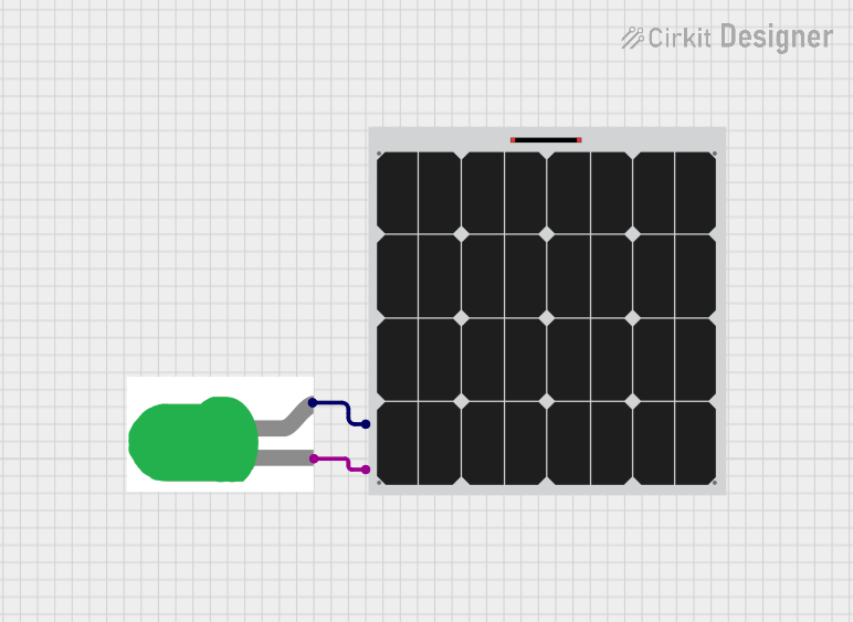
The Grove LED Bar is a versatile and easy-to-use 10-segment LED bar graph that provides a visual representation of voltage levels or discrete values. It is commonly used in projects that require a simple yet effective way to display information, such as battery level indicators, signal strength displays, or progress indicators.
Explore Projects Built with Grove LED bar
Explore Projects Built with Grove LED bar
Common Applications and Use Cases
- Battery level indicators
- Signal strength displays for wireless communication
- Progress bars for task completion
- Visual alerts and status indicators
- Educational tools for teaching electronics and programming
Technical Specifications
The Grove LED Bar is designed to be interfaced with microcontrollers such as the Arduino UNO. Below are the key technical specifications:
- Operating Voltage: 3.3V to 5V
- LED Color: Typically green, yellow, or red segments
- Communication: Digital (uses a single data pin for control)
- Dimensions: 40mm x 20mm
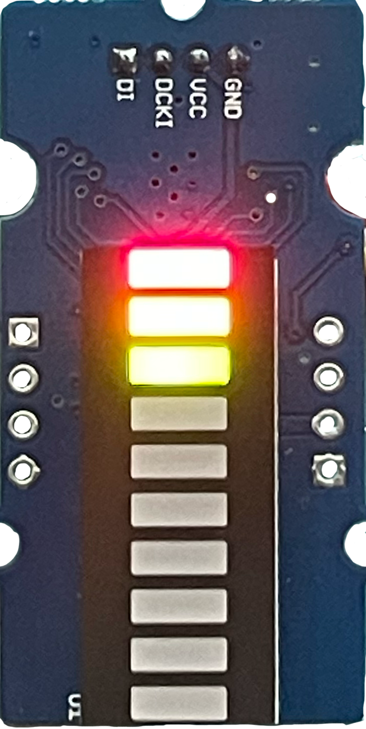
Pin Configuration and Descriptions
| Pin Number | Description |
|---|---|
| 1 | GND (Ground) |
| 2 | VCC (Supply Voltage) |
| 3 | DCKI (Clock Input) |
| 4 | DI (Data Input) |
Usage Instructions
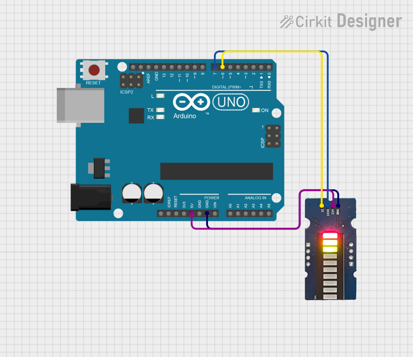
Connecting to an Arduino UNO
- Connect the GND pin of the Grove LED Bar to the GND pin on the Arduino.
- Connect the VCC pin to a 5V output on the Arduino.
- Connect the DCKI pin to a digital pin on the Arduino (e.g., D2).
- Connect the DI pin to another digital pin (e.g., D3).
Programming the Grove LED Bar
To control the LED bar, you will need to send digital signals to the DCKI and DI pins. Here is a sample code snippet for the Arduino UNO:
#include "Grove_LED_Bar.h"

Grove_LED_Bar bar(D3, D2, 0); // DI pin, DCKI pin, orientation

void setup() {
  bar.begin(); // Initialize the LED bar
}

void loop() {
  for (int i = 0; i <= 10; i++) {
    bar.setLevel(i); // Set the LED bar level (0-10)
    delay(100); // Wait for 100 milliseconds
  }
}
Important Considerations and Best Practices
- Ensure that the supply voltage does not exceed the maximum rating of 5V.
- When connecting to a microcontroller, use current-limiting resistors if necessary.
- Avoid looking directly into the LEDs to prevent eye strain or damage.
Troubleshooting and FAQs
Common Issues
- LEDs not lighting up: Check the connections and ensure that the supply voltage is within the specified range.
- Only some LEDs are working: This could be due to a partial connection issue or a faulty LED. Check the solder joints and replace the module if necessary.
Solutions and Tips for Troubleshooting
- Double-check wiring against the pin configuration table.
- Verify that the correct pins are used in the code.
- Use a multimeter to check for continuity and proper voltage levels.
FAQs
Q: Can I control the brightness of the LEDs? A: Yes, the Grove LED Bar allows for brightness control through PWM (Pulse Width Modulation).
Q: Is it possible to display multiple colors? A: The color of the LEDs is fixed. However, some models may have multiple colors in a single bar (e.g., green to red).
Q: How do I reverse the direction of the LED indicators? A: You can reverse the direction by changing the orientation parameter in the constructor to 1.
Q: Can I use the Grove LED Bar with a 3.3V system? A: Yes, the Grove LED Bar can operate at 3.3V, but the brightness of the LEDs may be reduced.
This documentation provides a comprehensive guide to using the Grove LED Bar with an Arduino UNO. For further assistance or more advanced usage, refer to the manufacturer's datasheet and additional resources.