
How to Use GY-VL53L0XV2 LASER TOF SENSOR: Examples, Pinouts, and Specs
 Design with GY-VL53L0XV2 LASER TOF SENSOR in Cirkit Designer
Introduction
The GY-VL53L0XV2 is a compact and highly accurate time-of-flight (ToF) sensor module that uses laser technology to measure distances. It operates by emitting a laser pulse and calculating the time it takes for the pulse to reflect back to the sensor, enabling precise distance measurements. This sensor is ideal for applications such as robotics, automation, obstacle detection, and proximity sensing. Its small size and low power consumption make it suitable for integration into a wide range of projects.
Explore Projects Built with GY-VL53L0XV2 LASER TOF SENSOR
 Open Project in Cirkit Designer
 Open Project in Cirkit Designer
 Open Project in Cirkit Designer
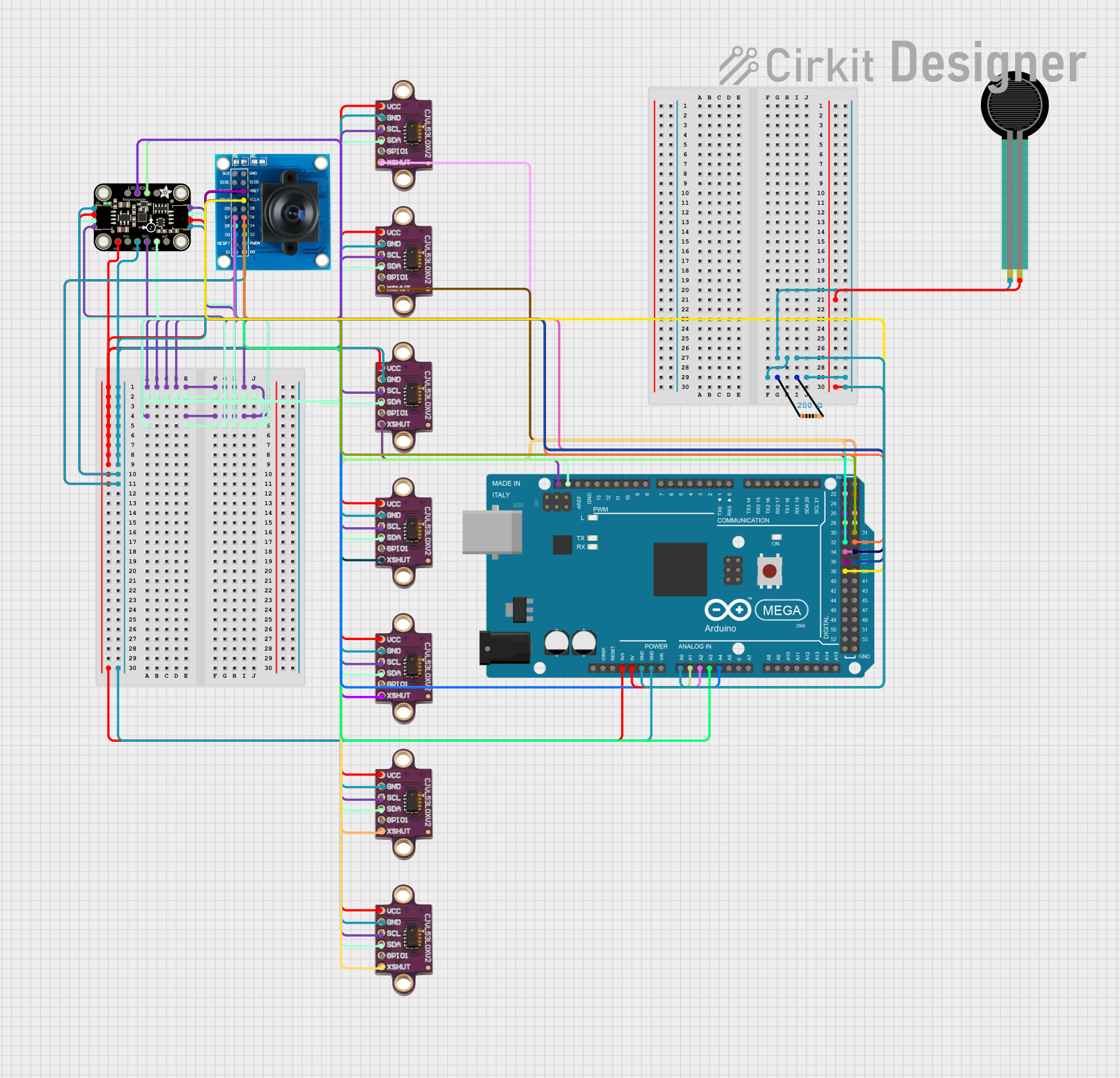 Open Project in Cirkit Designer
Explore Projects Built with GY-VL53L0XV2 LASER TOF SENSOR
Open Project in Cirkit DesignerOpen Project in Cirkit DesignerOpen Project in Cirkit DesignerOpen Project in Cirkit DesignerTechnical Specifications
- Model: GY-VL53L0XV2
- Measurement Range: 30 mm to 2000 mm (2 meters)
- Accuracy: ±3% under optimal conditions
- Operating Voltage: 2.6V to 5.5V
- Communication Interface: I²C (Inter-Integrated Circuit)
- I²C Address: Default 0x29 (modifiable)
- Current Consumption: 10 mA (typical)
- Field of View (FoV): 25°
- Operating Temperature: -20°C to +70°C
- Dimensions: 10 mm x 13 mm
Pin Configuration and Descriptions
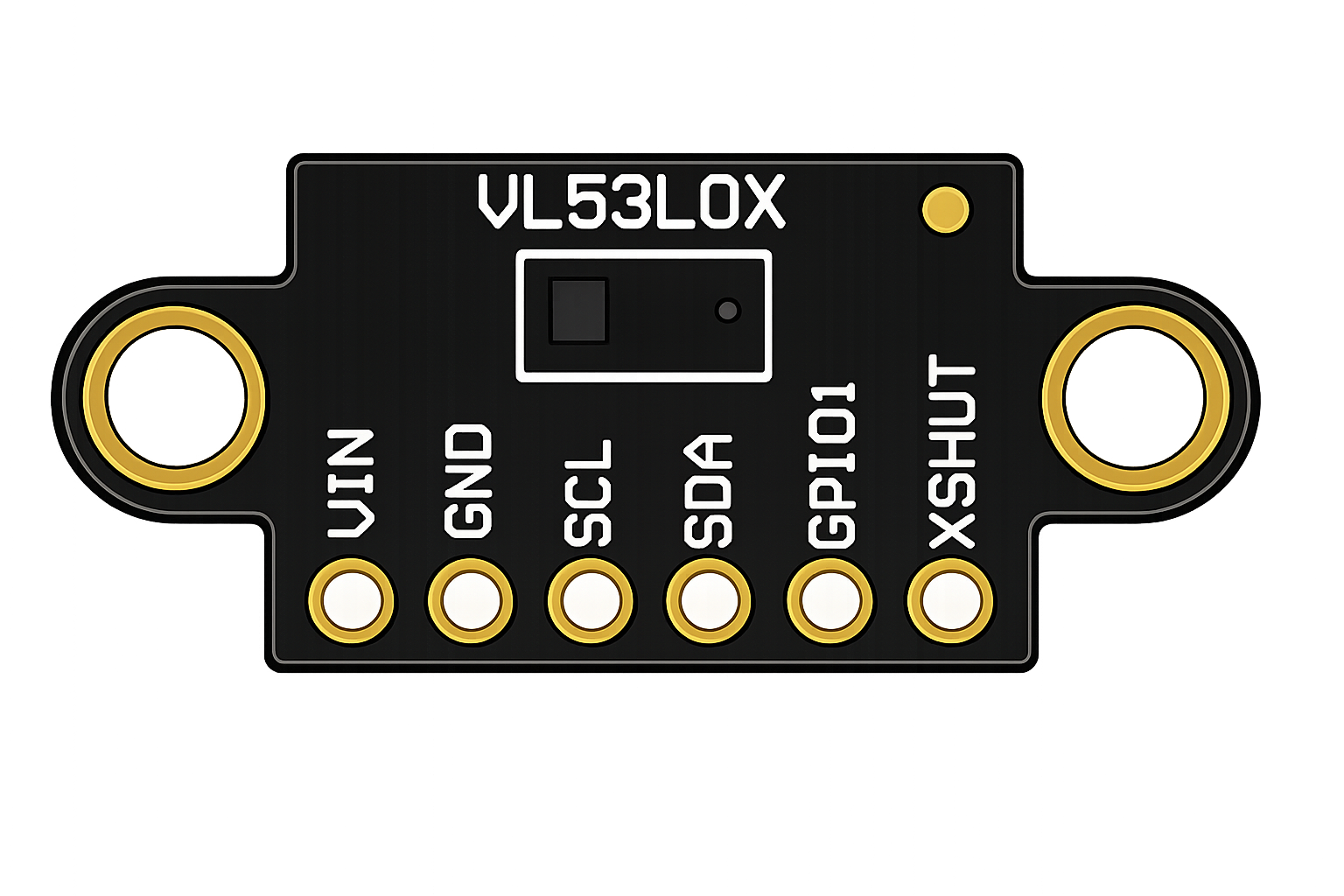
The GY-VL53L0XV2 module typically has six pins. Below is the pinout and description:
| Pin | Name | Description |
|---|---|---|
| 1 | VIN | Power supply input (2.6V to 5.5V). Connect to the 5V or 3.3V pin of your microcontroller. |
| 2 | GND | Ground. Connect to the ground of your circuit. |
| 3 | SDA | I²C data line. Used for communication with the microcontroller. |
| 4 | SCL | I²C clock line. Used for communication with the microcontroller. |
| 5 | XSHUT | Shutdown pin. Pull low to put the sensor in shutdown mode. |
| 6 | GPIO1 | Interrupt pin. Can be used for advanced configurations. |
Usage Instructions
How to Use the GY-VL53L0XV2 in a Circuit
- Power the Sensor: Connect the VIN pin to a 3.3V or 5V power source and the GND pin to the ground.
- I²C Communication: Connect the SDA and SCL pins to the corresponding I²C pins on your microcontroller. Use pull-up resistors (typically 4.7kΩ) if not already present on the module.
- Optional Pins:
- Connect the XSHUT pin to a GPIO pin on your microcontroller if you need to control the sensor's power state.
- Use the GPIO1 pin for interrupt-based applications if required.
- Install Libraries: If using an Arduino, install the VL53L0X library from the Arduino Library Manager for easy integration.
Important Considerations and Best Practices
- Ensure the sensor is not exposed to direct sunlight or reflective surfaces, as these can interfere with measurements.
- Avoid placing the sensor too close to the object being measured (minimum range is 30 mm).
- Use short and properly shielded wires for I²C connections to minimize noise.
- If multiple VL53L0X sensors are used on the same I²C bus, modify their I²C addresses to avoid conflicts.
Example Code for Arduino UNO
Below is an example of how to use the GY-VL53L0XV2 with an Arduino UNO:
#include <Wire.h>
#include <VL53L0X.h>

// Create an instance of the VL53L0X sensor
VL53L0X sensor;

void setup() {
  Serial.begin(9600); // Initialize serial communication for debugging
  Wire.begin();       // Initialize I²C communication

  // Initialize the sensor
  if (!sensor.init()) {
    Serial.println("Failed to initialize VL53L0X sensor!");
    while (1); // Halt execution if initialization fails
  }

  sensor.setTimeout(500); // Set a timeout for distance measurements
  Serial.println("VL53L0X sensor initialized successfully.");
}

void loop() {
  // Measure distance in millimeters
  uint16_t distance = sensor.readRangeSingleMillimeters();

  // Check for timeout errors
  if (sensor.timeoutOccurred()) {
    Serial.println("Sensor timeout occurred!");
  } else {
    // Print the measured distance
    Serial.print("Distance: ");
    Serial.print(distance);
    Serial.println(" mm");
  }

  delay(100); // Wait 100ms before the next measurement
}
Notes on the Code
- The
VL53L0Xlibrary simplifies communication with the sensor. - The
setTimeout()function prevents the program from hanging if the sensor fails to respond. - Modify the
delay()value in theloop()function to adjust the measurement frequency.
Troubleshooting and FAQs
Common Issues and Solutions
Sensor Not Detected on I²C Bus:
- Ensure the SDA and SCL connections are correct.
- Check for proper pull-up resistors on the I²C lines.
- Verify the sensor's I²C address (default is 0x29).
Incorrect Distance Measurements:
- Ensure the sensor is not too close to the object (minimum range is 30 mm).
- Avoid reflective or transparent surfaces in the sensor's field of view.
- Check for obstructions or dirt on the sensor's lens.
Sensor Timeout Errors:
- Increase the timeout value using the
setTimeout()function. - Verify that the sensor is powered correctly and not in shutdown mode.
- Increase the timeout value using the
Multiple Sensors on the Same I²C Bus:
- Use the XSHUT pin to reset individual sensors and assign unique I²C addresses.
FAQs
Q: Can the GY-VL53L0XV2 measure distances beyond 2 meters?
A: No, the maximum range of the sensor is 2 meters under optimal conditions.
Q: Is the laser emitted by the sensor safe for human eyes?
A: Yes, the VL53L0X uses a Class 1 laser, which is safe for human eyes under normal operating conditions.
Q: Can I use this sensor with a 3.3V microcontroller?
A: Yes, the sensor is compatible with both 3.3V and 5V systems.
Q: How do I modify the I²C address of the sensor?
A: Use the XSHUT pin to reset the sensor, then configure a new address in your code before reinitializing it.
By following this documentation, you can effectively integrate the GY-VL53L0XV2 LASER ToF sensor into your projects for accurate distance measurement.