How to Use Lux Flow Through O2 Sensor: Examples, Pinouts, and Specs
Introduction
The Lux Flow Through O2 Sensor by Luminox is a high-precision sensor designed to measure the concentration of oxygen in a flowing gas stream. This sensor is ideal for applications requiring continuous monitoring of oxygen levels, such as environmental monitoring, industrial processes, medical devices, and laboratory experiments. Its robust design ensures reliable performance in demanding environments, making it a trusted choice for professionals.
Explore Projects Built with Lux Flow Through O2 Sensor
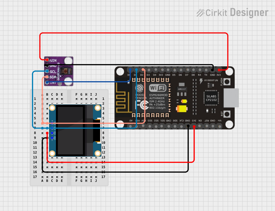
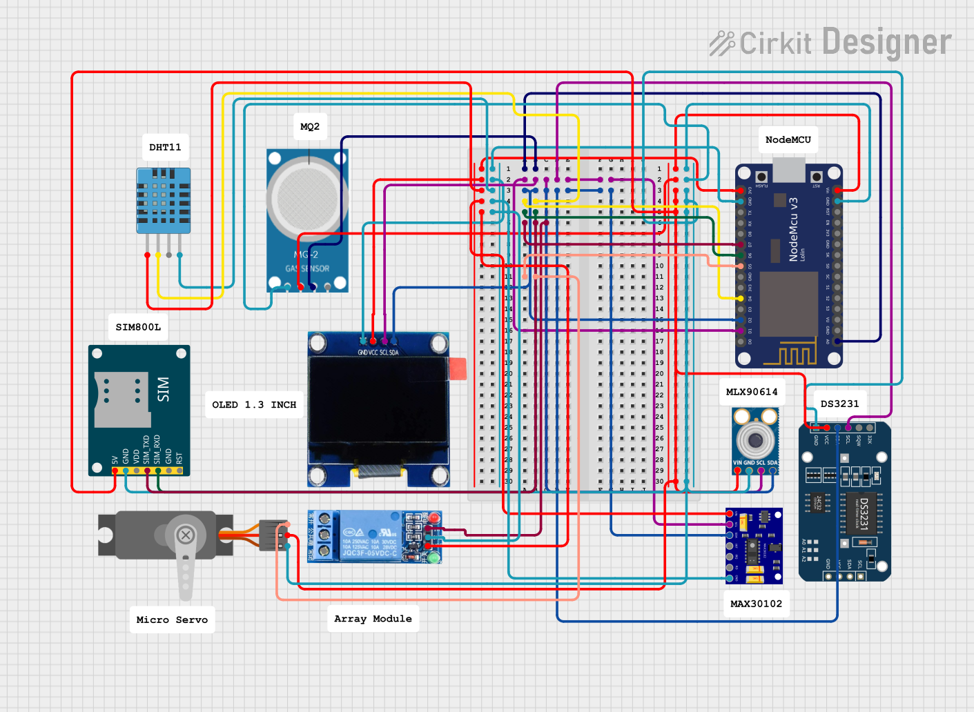
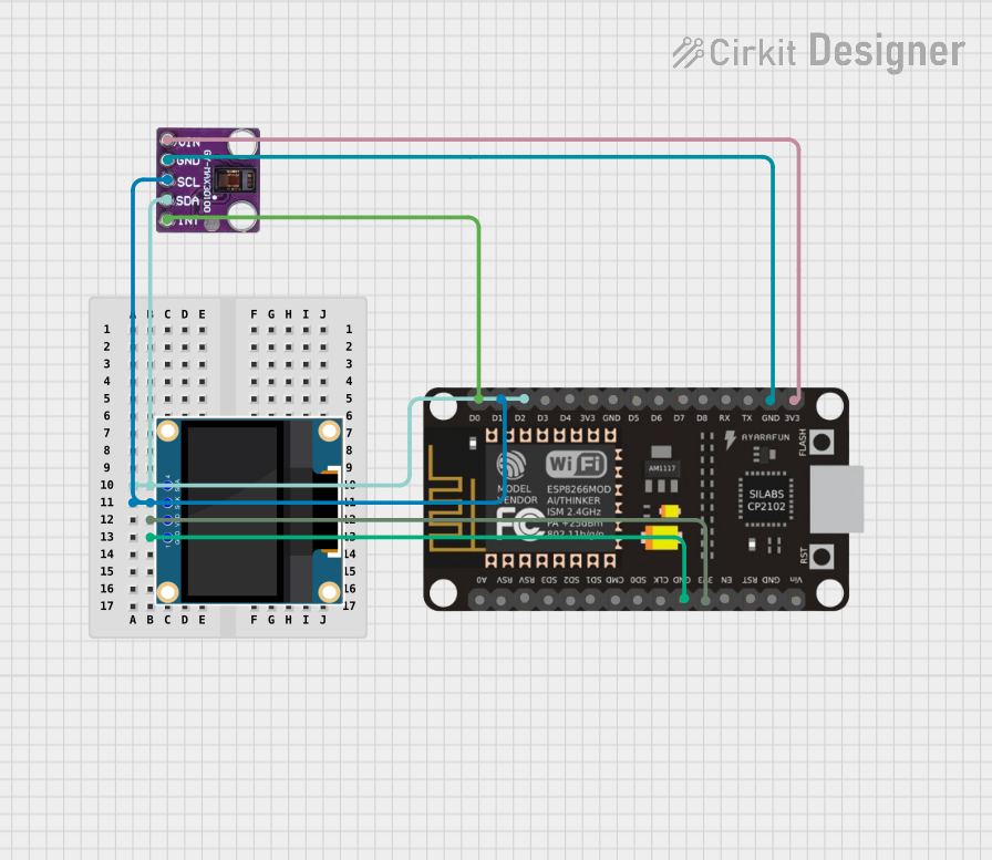
Explore Projects Built with Lux Flow Through O2 Sensor
Common Applications
- Environmental monitoring (e.g., air quality analysis)
- Industrial gas flow systems
- Medical oxygen monitoring
- Laboratory research and experiments
- Combustion control in industrial processes
Technical Specifications
The following table outlines the key technical details of the Lux Flow Through O2 Sensor:
| Parameter | Value |
|---|---|
| Measurement Range | 0% to 25% O₂ |
| Accuracy | ±1% of full scale |
| Response Time (T90) | < 15 seconds |
| Operating Temperature | -20°C to +50°C |
| Operating Pressure Range | 800 mbar to 1200 mbar |
| Output Signal | 0 to 5 V analog |
| Power Supply Voltage | 5 V DC |
| Power Consumption | < 50 mW |
| Gas Flow Rate | 0.1 to 1.0 L/min |
| Sensor Lifetime | > 5 years (typical) |
Pin Configuration
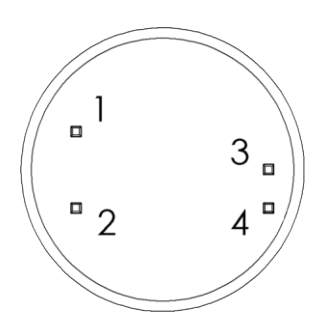
The Lux Flow Through O2 Sensor has a 4-pin interface. The pinout is described in the table below:
| Pin Number | Name | Description |
|---|---|---|
| 1 | VCC | Power supply input (5 V DC) |
| 2 | GND | Ground connection |
| 3 | Signal Out | Analog output signal proportional to O₂ level |
| 4 | NC (No Connect) | Not connected (leave unconnected in the circuit) |
Usage Instructions
How to Use the Sensor in a Circuit
- Power Supply: Connect the sensor's VCC pin to a stable 5 V DC power source and the GND pin to the ground of your circuit.
- Signal Output: The Signal Out pin provides an analog voltage proportional to the oxygen concentration. Connect this pin to an analog input of a microcontroller or data acquisition system.
- Gas Flow: Ensure the gas stream flows through the sensor at a rate between 0.1 and 1.0 L/min for accurate readings.
- Calibration: For best results, calibrate the sensor using a known oxygen concentration (e.g., ambient air at 20.9% O₂).
Important Considerations
- Avoid Contaminants: Ensure the gas stream is free of contaminants like oil, water vapor, or particulates, as these can affect sensor performance.
- Temperature and Pressure: Operate the sensor within the specified temperature and pressure ranges to maintain accuracy.
- Warm-Up Time: Allow the sensor to stabilize for a few minutes after powering it on before taking measurements.
- Signal Conditioning: If the output signal is noisy, consider adding a low-pass filter to smooth the signal.
Example: Connecting to an Arduino UNO
The following example demonstrates how to interface the Lux Flow Through O2 Sensor with an Arduino UNO to read and display oxygen concentration.
Circuit Diagram
- Connect the sensor's VCC pin to the Arduino's 5V pin.
- Connect the GND pin to the Arduino's GND pin.
- Connect the Signal Out pin to the Arduino's A0 analog input pin.
Arduino Code
// Lux Flow Through O2 Sensor Example Code
// Reads the analog output from the sensor and calculates oxygen concentration.

const int sensorPin = A0; // Analog pin connected to Signal Out
const float maxVoltage = 5.0; // Maximum output voltage of the sensor
const float maxOxygen = 25.0; // Maximum oxygen concentration (25%)

void setup() {
  Serial.begin(9600); // Initialize serial communication
  Serial.println("Lux Flow Through O2 Sensor Test");
}

void loop() {
  int sensorValue = analogRead(sensorPin); // Read analog value from sensor
  float voltage = (sensorValue / 1023.0) * maxVoltage; // Convert to voltage
  float oxygenConcentration = (voltage / maxVoltage) * maxOxygen;
  // Calculate oxygen concentration

  // Print the results to the Serial Monitor
  Serial.print("Voltage: ");
  Serial.print(voltage);
  Serial.print(" V, Oxygen Concentration: ");
  Serial.print(oxygenConcentration);
  Serial.println(" %");

  delay(1000); // Wait 1 second before the next reading
}
Troubleshooting and FAQs
Common Issues and Solutions
No Output Signal
- Cause: Incorrect wiring or no power supply.
- Solution: Verify all connections and ensure the sensor is powered with 5 V DC.
Inaccurate Readings
- Cause: Calibration not performed or gas flow rate outside the specified range.
- Solution: Calibrate the sensor using a known oxygen concentration and ensure the gas flow rate is between 0.1 and 1.0 L/min.
Slow Response Time
- Cause: Gas flow rate too low or sensor clogged.
- Solution: Increase the gas flow rate and check for blockages in the sensor.
Signal Noise
- Cause: Electrical interference or unstable power supply.
- Solution: Use a low-pass filter on the output signal and ensure a stable power source.
FAQs
Q: Can the sensor measure oxygen in liquids?
A: No, the Lux Flow Through O2 Sensor is designed for gas-phase oxygen measurement only.
Q: How often should the sensor be calibrated?
A: Calibration frequency depends on the application, but it is recommended to calibrate the sensor at least once every 6 months for critical applications.
Q: What happens if the sensor is exposed to high humidity?
A: Prolonged exposure to high humidity may affect the sensor's performance. Use a desiccant or humidity control measures if necessary.
Q: Can the sensor operate at altitudes above 2000 meters?
A: The sensor's performance may be affected at low pressures. Consult the manufacturer for high-altitude applications.
This documentation provides a comprehensive guide to using the Lux Flow Through O2 Sensor effectively. For further assistance, refer to the manufacturer's datasheet or contact Luminox support.