How to Use BioAmp EXG PILL: Examples, Pinouts, and Specs
Introduction
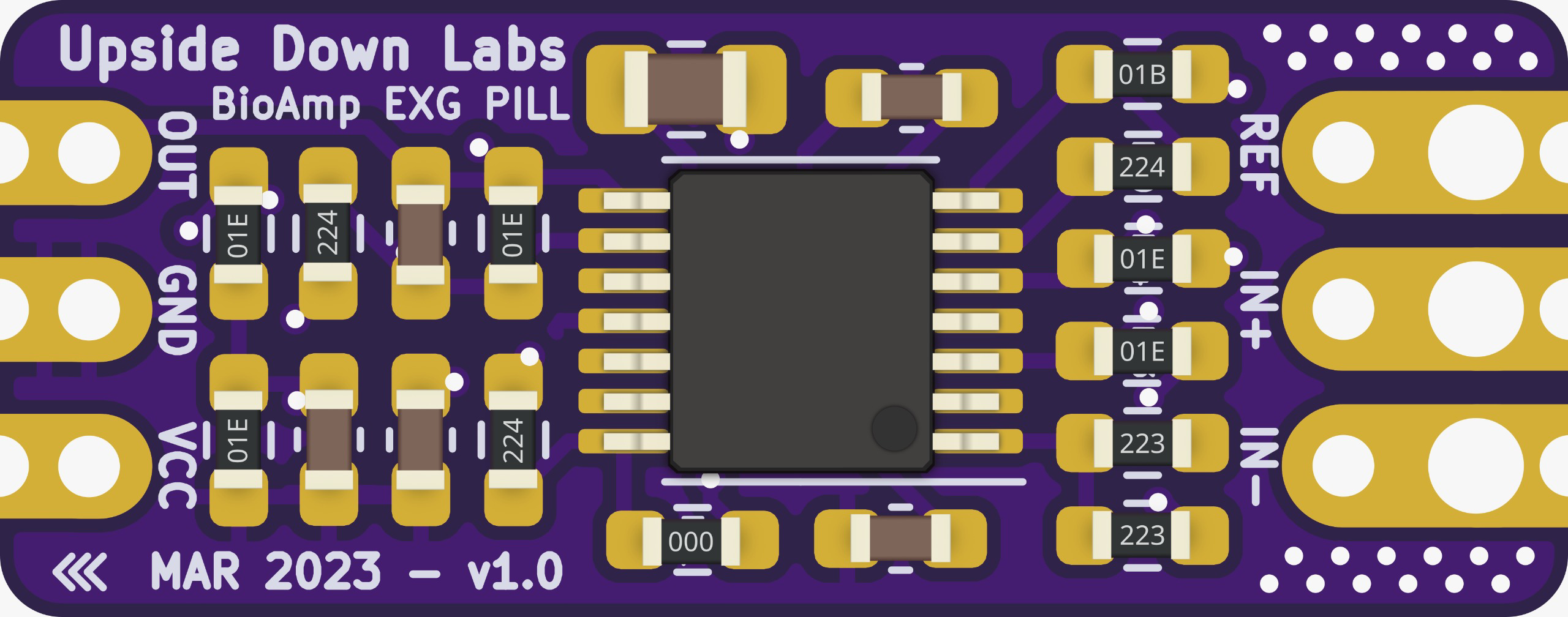
The BioAmp EXG PILL by Upside Down Labs (Part ID: EXG PILL) is a small, versatile biopotential amplifier designed for capturing high-quality electrophysiological signals such as ECG (Electrocardiography), EMG (Electromyography), and EEG (Electroencephalography). This component is ideal for applications in biomedical research, health monitoring, and biofeedback systems.
Explore Projects Built with BioAmp EXG PILL
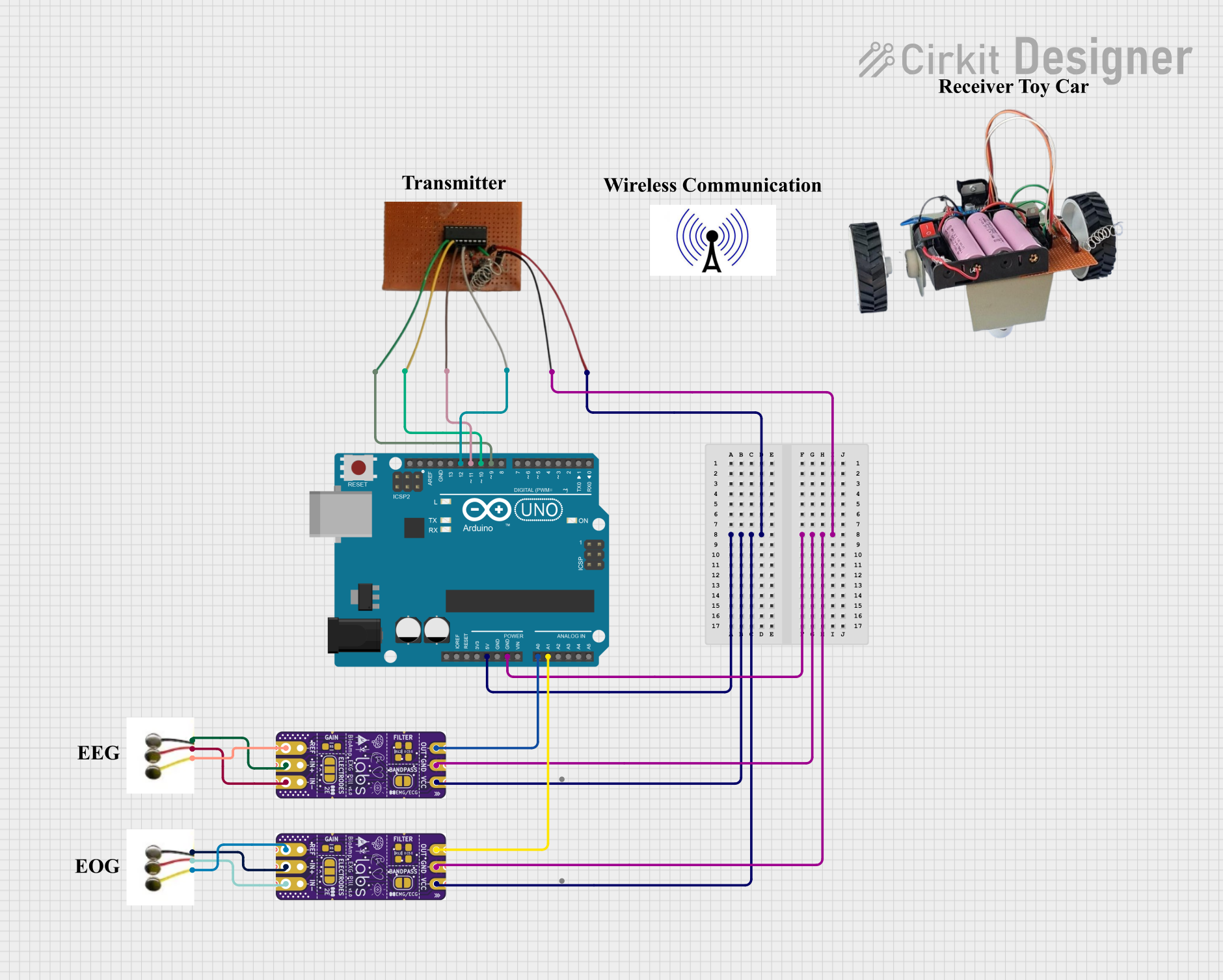

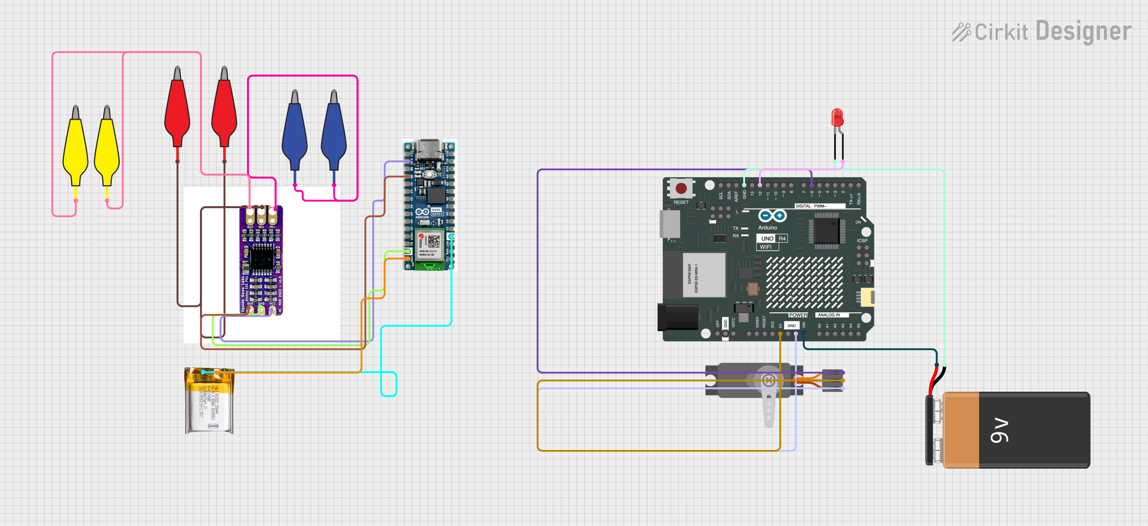
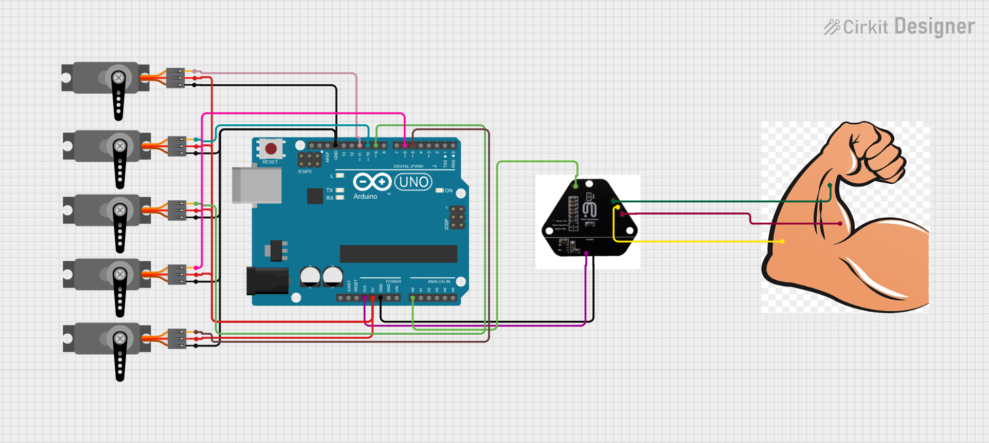
Explore Projects Built with BioAmp EXG PILL
Technical Specifications
Key Technical Details
| Parameter | Value |
|---|---|
| Supply Voltage | 3.3V - 5V |
| Operating Current | 1.5mA |
| Gain | 1000x |
| Input Impedance | >10 GΩ |
| Bandwidth | 0.5 Hz - 100 Hz |
| Output Voltage | 0 - 3.3V |
| Dimensions | 20mm x 20mm |
Pin Configuration and Descriptions
| Pin | Name | Description |
|---|---|---|
| 1 | VCC | Power supply (3.3V - 5V) |
| 2 | GND | Ground |
| 3 | IN+ | Non-inverting input for biopotential signal |
| 4 | IN- | Inverting input for biopotential signal |
| 5 | OUT | Amplified output signal |
| 6 | REF | Reference voltage (typically connected to GND) |
Usage Instructions
How to Use the Component in a Circuit
- Power Supply: Connect the VCC pin to a 3.3V or 5V power supply and the GND pin to the ground of your circuit.
- Signal Input: Connect the biopotential signal source to the IN+ and IN- pins. For differential measurements, connect the signal to both pins. For single-ended measurements, connect the signal to IN+ and the reference (e.g., GND) to IN-.
- Reference Voltage: Connect the REF pin to the ground (GND) to set the reference voltage.
- Signal Output: The amplified signal can be read from the OUT pin. This output can be connected to an ADC (Analog-to-Digital Converter) for digital processing.
Important Considerations and Best Practices
- Electrode Placement: Ensure proper placement of electrodes to minimize noise and obtain accurate readings.
- Shielding: Use shielded cables to reduce electromagnetic interference.
- Filtering: Implement additional filtering if necessary to remove unwanted noise from the signal.
- Calibration: Regularly calibrate the system to maintain accuracy.
Example Code for Arduino UNO
Below is an example code to read the amplified signal from the BioAmp EXG PILL using an Arduino UNO:
// Define the analog pin connected to the OUT pin of BioAmp EXG PILL
const int bioAmpPin = A0;

void setup() {
  // Initialize serial communication at 9600 baud rate
  Serial.begin(9600);
}

void loop() {
  // Read the analog value from the BioAmp EXG PILL
  int sensorValue = analogRead(bioAmpPin);

  // Convert the analog value to voltage (assuming 5V reference)
  float voltage = sensorValue * (5.0 / 1023.0);

  // Print the voltage to the serial monitor
  Serial.print("Voltage: ");
  Serial.println(voltage);

  // Delay for a short period to avoid flooding the serial monitor
  delay(100);
}
Troubleshooting and FAQs
Common Issues Users Might Face
No Signal Output:
- Solution: Check the power supply connections and ensure the VCC and GND pins are properly connected.
- Solution: Verify that the input signal is correctly connected to the IN+ and IN- pins.
Noisy Signal:
- Solution: Ensure proper electrode placement and use shielded cables to minimize interference.
- Solution: Implement additional filtering to remove unwanted noise.
Incorrect Readings:
- Solution: Calibrate the system regularly to maintain accuracy.
- Solution: Check for loose connections and ensure all pins are securely connected.
FAQs
Q1: Can the BioAmp EXG PILL be used with a 3.3V power supply?
- A1: Yes, the BioAmp EXG PILL can operate with a power supply ranging from 3.3V to 5V.
Q2: What type of signals can the BioAmp EXG PILL amplify?
- A2: The BioAmp EXG PILL is designed to amplify biopotential signals such as ECG, EMG, and EEG.
Q3: How can I reduce noise in the signal?
- A3: Use proper electrode placement, shielded cables, and additional filtering to reduce noise.
Q4: Can I use the BioAmp EXG PILL with other microcontrollers besides Arduino?
- A4: Yes, the BioAmp EXG PILL can be used with any microcontroller that has an ADC input.
This documentation provides a comprehensive guide to using the BioAmp EXG PILL. Whether you are a beginner or an experienced user, following these instructions and best practices will help you achieve accurate and reliable biopotential signal measurements.