Cirkit Designer Logo
Cirkit Designer
Your all-in-one circuit design IDE
Home / 
Component Documentation

How to Use XY-MD02: Examples, Pinouts, and Specs

Image of XY-MD02
Cirkit Designer LogoDesign with XY-MD02 in Cirkit Designer

Introduction

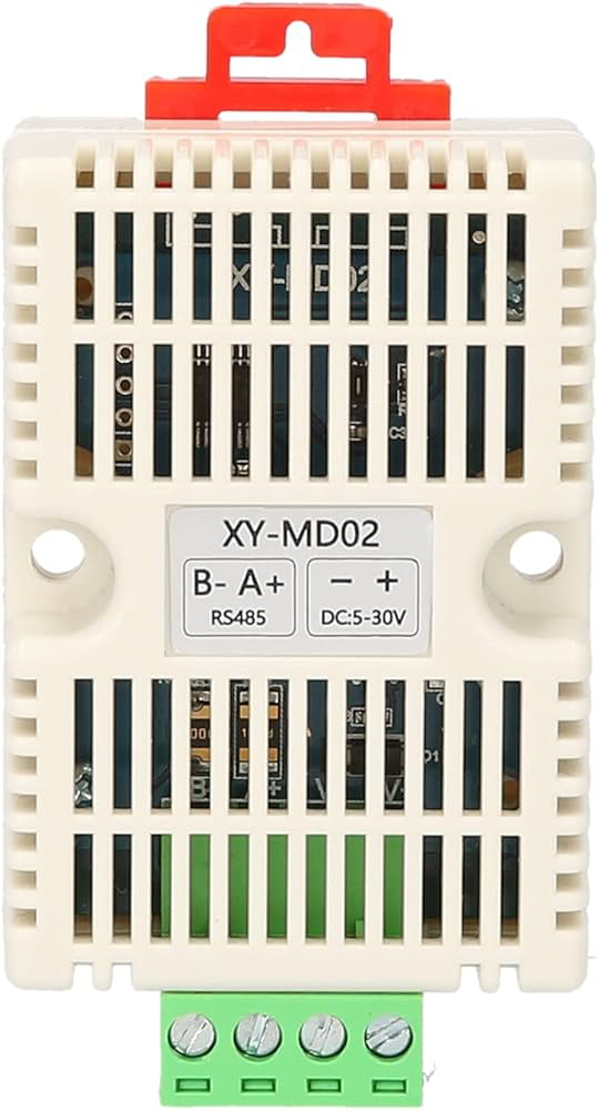
The XY-MD02 is a versatile motor driver module designed to control the speed and direction of DC motors. It is commonly used in robotics, automation projects, and various DIY applications where precise motor control is required. The module typically supports features such as variable speed control, bidirectional control, and dynamic braking, making it an essential component for projects that require reliable and efficient motor management.

Explore Projects Built with XY-MD02

Use Cirkit Designer to design, explore, and prototype these projects online. Some projects support real-time simulation. Click "Open Project" to start designing instantly!
Battery-Powered Health Monitoring System with Nucleo WB55RG and OLED Display
Image of Pulsefex: A project utilizing XY-MD02 in a practical application
This circuit is a multi-sensor data acquisition system that uses a Nucleo WB55RG microcontroller to interface with a digital temperature sensor (TMP102), a pulse oximeter and heart-rate sensor (MAX30102), and a 0.96" OLED display via I2C. Additionally, it includes a Sim800l module for GSM communication, powered by a 3.7V LiPo battery.
Cirkit Designer LogoOpen Project in Cirkit Designer
Arduino Mega 2560 Controlled Motor System with I2C Communication and Hall Effect Sensing
Image of Uni1: A project utilizing XY-MD02 in a practical application
This is a motor control system with feedback and sensor integration. It uses an Arduino Mega 2560 to control MD03 motor drivers for DC motors, receives position and speed feedback from HEDS encoders and Hall sensors, and measures distance with SR02 ultrasonic sensors. Logic level converters ensure compatibility between different voltage levels of the components.
Cirkit Designer LogoOpen Project in Cirkit Designer
Wireless Joystick-Controlled Interface with Arduino Nano and NRF24L01
Image of Transmitter 11: A project utilizing XY-MD02 in a practical application
This circuit features an Arduino Nano interfaced with a KY-023 Dual Axis Joystick Module for analog input, and an NRF24L01 module for wireless communication. The joystick provides x and y-axis control signals to the Arduino's analog inputs and a switch signal to a digital input, while the NRF24L01 enables the Arduino to communicate with other devices wirelessly. The 2x 18650 batteries supply power to the Arduino, which in turn powers the joystick and the NRF24L01 module.
Cirkit Designer LogoOpen Project in Cirkit Designer
Arduino Nano-Based Wireless Joystick and Motion Controller
Image of hand gesture: A project utilizing XY-MD02 in a practical application
This circuit features an Arduino Nano microcontroller interfaced with an HC-05 Bluetooth module, an MPU-6050 accelerometer/gyroscope, and a KY-023 Dual Axis Joystick Module. The Arduino Nano is powered by a 9V battery through a rocker switch and communicates with the HC-05 for Bluetooth connectivity, reads joystick positions from the KY-023 module via analog inputs, and communicates with the MPU-6050 over I2C to capture motion data. The circuit is likely designed for wireless control and motion sensing applications, such as a remote-controlled robot or a game controller.
Cirkit Designer LogoOpen Project in Cirkit Designer

Explore Projects Built with XY-MD02

Use Cirkit Designer to design, explore, and prototype these projects online. Some projects support real-time simulation. Click "Open Project" to start designing instantly!
Image of Pulsefex: A project utilizing XY-MD02 in a practical application
Battery-Powered Health Monitoring System with Nucleo WB55RG and OLED Display
This circuit is a multi-sensor data acquisition system that uses a Nucleo WB55RG microcontroller to interface with a digital temperature sensor (TMP102), a pulse oximeter and heart-rate sensor (MAX30102), and a 0.96" OLED display via I2C. Additionally, it includes a Sim800l module for GSM communication, powered by a 3.7V LiPo battery.
Cirkit Designer LogoOpen Project in Cirkit Designer
Image of Uni1: A project utilizing XY-MD02 in a practical application
Arduino Mega 2560 Controlled Motor System with I2C Communication and Hall Effect Sensing
This is a motor control system with feedback and sensor integration. It uses an Arduino Mega 2560 to control MD03 motor drivers for DC motors, receives position and speed feedback from HEDS encoders and Hall sensors, and measures distance with SR02 ultrasonic sensors. Logic level converters ensure compatibility between different voltage levels of the components.
Cirkit Designer LogoOpen Project in Cirkit Designer
Image of Transmitter 11: A project utilizing XY-MD02 in a practical application
Wireless Joystick-Controlled Interface with Arduino Nano and NRF24L01
This circuit features an Arduino Nano interfaced with a KY-023 Dual Axis Joystick Module for analog input, and an NRF24L01 module for wireless communication. The joystick provides x and y-axis control signals to the Arduino's analog inputs and a switch signal to a digital input, while the NRF24L01 enables the Arduino to communicate with other devices wirelessly. The 2x 18650 batteries supply power to the Arduino, which in turn powers the joystick and the NRF24L01 module.
Cirkit Designer LogoOpen Project in Cirkit Designer
Image of hand gesture: A project utilizing XY-MD02 in a practical application
Arduino Nano-Based Wireless Joystick and Motion Controller
This circuit features an Arduino Nano microcontroller interfaced with an HC-05 Bluetooth module, an MPU-6050 accelerometer/gyroscope, and a KY-023 Dual Axis Joystick Module. The Arduino Nano is powered by a 9V battery through a rocker switch and communicates with the HC-05 for Bluetooth connectivity, reads joystick positions from the KY-023 module via analog inputs, and communicates with the MPU-6050 over I2C to capture motion data. The circuit is likely designed for wireless control and motion sensing applications, such as a remote-controlled robot or a game controller.
Cirkit Designer LogoOpen Project in Cirkit Designer

Common Applications and Use Cases

  • Robotics: Driving motors for robotic arms, wheels, or tracks.
  • Automation Systems: Controlling actuators in automated machinery.
  • Hobby Projects: Managing motors in model vehicles or custom-built machines.
  • Educational Purposes: Teaching the principles of motor control in STEM programs.

Technical Specifications

Key Technical Details

  • Operating Voltage: Typically ranges from 6V to 30V.
  • Continuous Current Rating: Up to a certain limit, often around 3A to 10A.
  • Peak Current Rating: A higher current for short durations, subject to module design.
  • Control Signal Voltage: Compatible with standard logic levels (e.g., 5V).
  • Control Method: PWM (Pulse Width Modulation) for speed control, logic inputs for direction.

Pin Configuration and Descriptions

Pin Number Pin Name Description
1 VCC Power supply for the motor (6V-30V)
2 GND Ground connection
3 AIN1 Direction control input 1
4 AIN2 Direction control input 2
5 PWMA PWM input for speed control
6 STBY Standby mode activation (active low)
7 BIN1 Direction control input for second motor (if applicable)
8 BIN2 Direction control input for second motor (if applicable)
9 PWMB PWM input for second motor speed control (if applicable)

Usage Instructions

How to Use the Component in a Circuit

  1. Power Connections: Connect the VCC and GND pins to your DC power supply, ensuring it matches the module's voltage requirements.
  2. Motor Connections: Attach the motor's leads to the output terminals of the XY-MD02.
  3. Control Signal Connections: Connect AIN1 and AIN2 to your control circuitry (e.g., microcontroller) to set the motor's direction. Connect PWMA to a PWM-capable pin on your controller for speed control.
  4. Standby Mode: Optionally, connect the STBY pin to a digital output on your controller to enable or disable the motor driver.

Important Considerations and Best Practices

  • Ensure the power supply does not exceed the maximum voltage rating of the module.
  • Do not exceed the continuous current rating to prevent overheating and potential damage.
  • Use a PWM frequency that is within the module's operating range for optimal performance.
  • Implement proper cooling if operating near the current limits or in high-temperature environments.
  • Always double-check wiring before powering up to prevent shorts and component damage.

Troubleshooting and FAQs

Common Issues Users Might Face

  • Motor not spinning: Check power supply connections, ensure control signals are being sent, and verify that the STBY pin is not active (low).
  • Overheating: Reduce the load on the motor, improve cooling, or check for shorts in the wiring.
  • Inconsistent motor speed: Ensure PWM signal is stable and within the correct frequency range.

Solutions and Tips for Troubleshooting

  • Use a multimeter to verify power supply voltage and continuity in connections.
  • Test the control signals with an oscilloscope to ensure they are within specifications.
  • If the motor driver enters a protection mode, disconnect power, check for issues, and then reconnect.

Example Code for Arduino UNO

// Define control pins
const int pwmPin = 3; // PWMA pin connected to Arduino pin 3
const int dirPin1 = 4; // AIN1 pin connected to Arduino pin 4
const int dirPin2 = 5; // AIN2 pin connected to Arduino pin 5

void setup() {
  // Set control pins as outputs
  pinMode(pwmPin, OUTPUT);
  pinMode(dirPin1, OUTPUT);
  pinMode(dirPin2, OUTPUT);
}

void loop() {
  // Set motor direction to forward
  digitalWrite(dirPin1, HIGH);
  digitalWrite(dirPin2, LOW);

  // Ramp up the speed
  for (int speed = 0; speed <= 255; speed++) {
    analogWrite(pwmPin, speed);
    delay(10);
  }

  // Ramp down the speed
  for (int speed = 255; speed >= 0; speed--) {
    analogWrite(pwmPin, speed);
    delay(10);
  }

  // Change motor direction to reverse
  digitalWrite(dirPin1, LOW);
  digitalWrite(dirPin2, HIGH);

  // Repeat the ramp up and down for reverse direction
  for (int speed = 0; speed <= 255; speed++) {
    analogWrite(pwmPin, speed);
    delay(10);
  }
  for (int speed = 255; speed >= 0; speed--) {
    analogWrite(pwmPin, speed);
    delay(10);
  }
}

This example demonstrates basic forward and reverse control of a DC motor using the XY-MD02 motor driver module with an Arduino UNO. The analogWrite function is used to control the speed of the motor through PWM, while the digitalWrite functions set the direction. The motor speed is ramped up and down in both forward and reverse directions.