
How to Use Momentary Switch: Examples, Pinouts, and Specs

 Design with Momentary Switch in Cirkit Designer
Introduction
A momentary switch is a type of switch that only remains in the 'on' position while being pressed. Once released, it automatically returns to its 'off' position. This behavior makes it ideal for applications where a temporary connection is required. Common use cases include doorbells, keyboard keys, and control panels. Momentary switches are widely used in both consumer electronics and industrial systems due to their simplicity and reliability.
Explore Projects Built with Momentary Switch
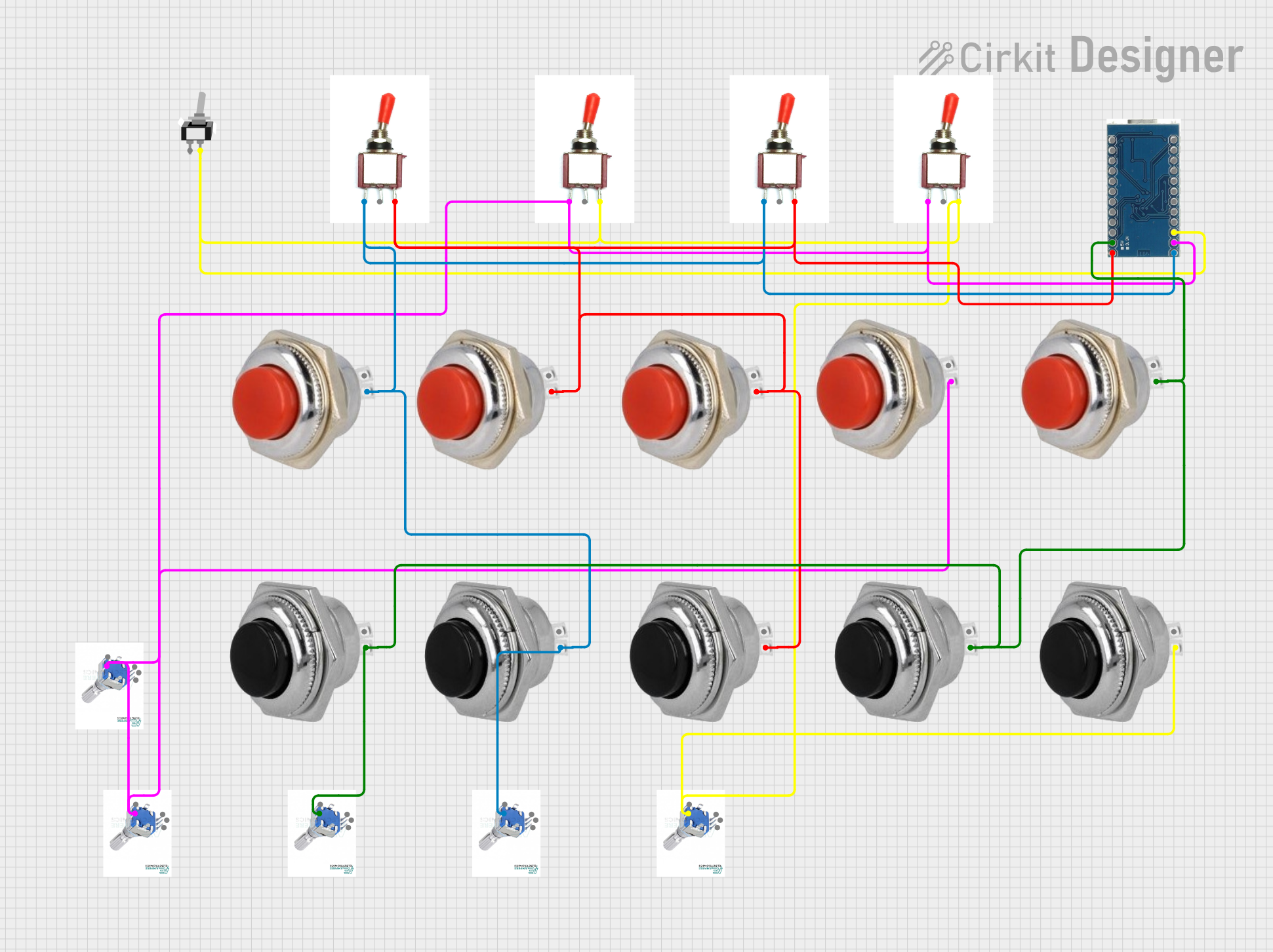 Open Project in Cirkit Designer
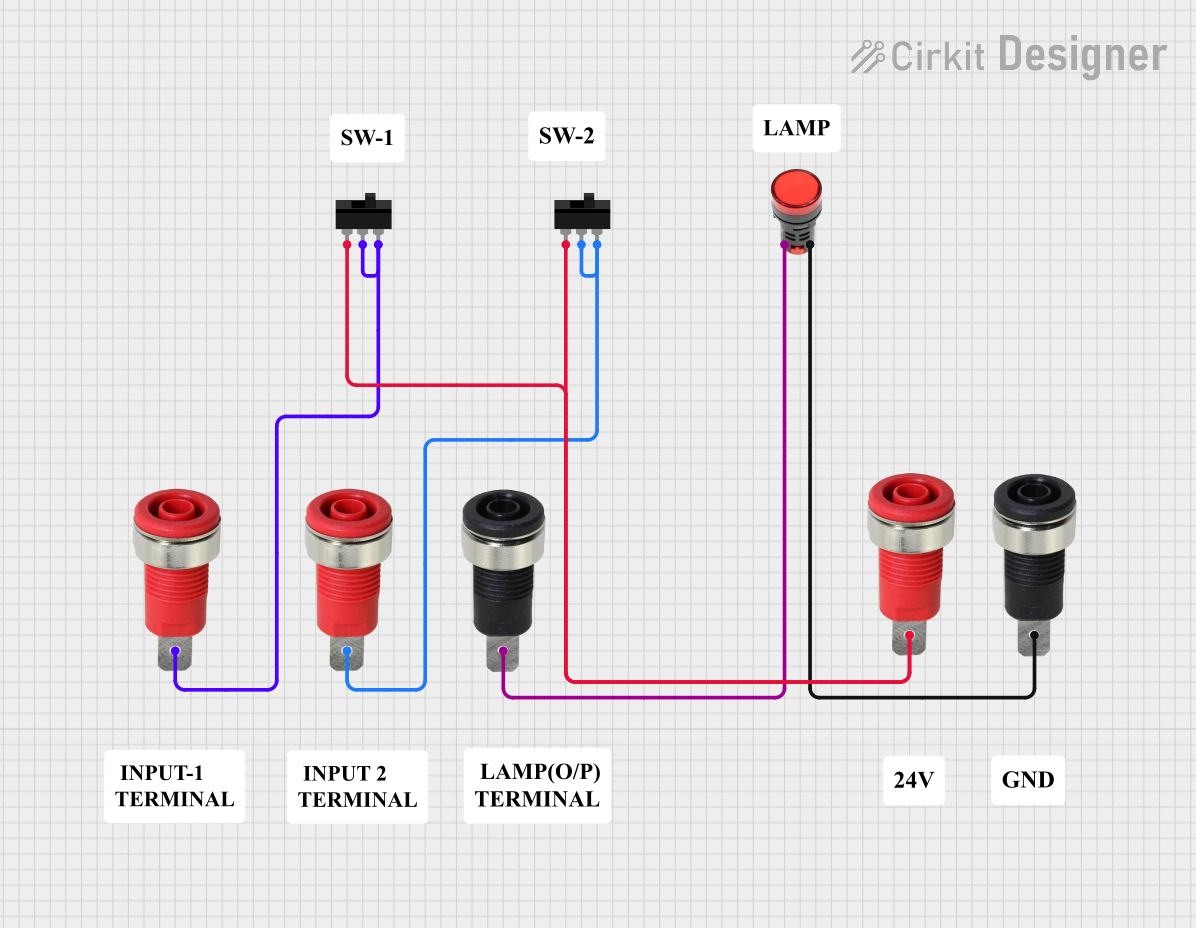 Open Project in Cirkit Designer
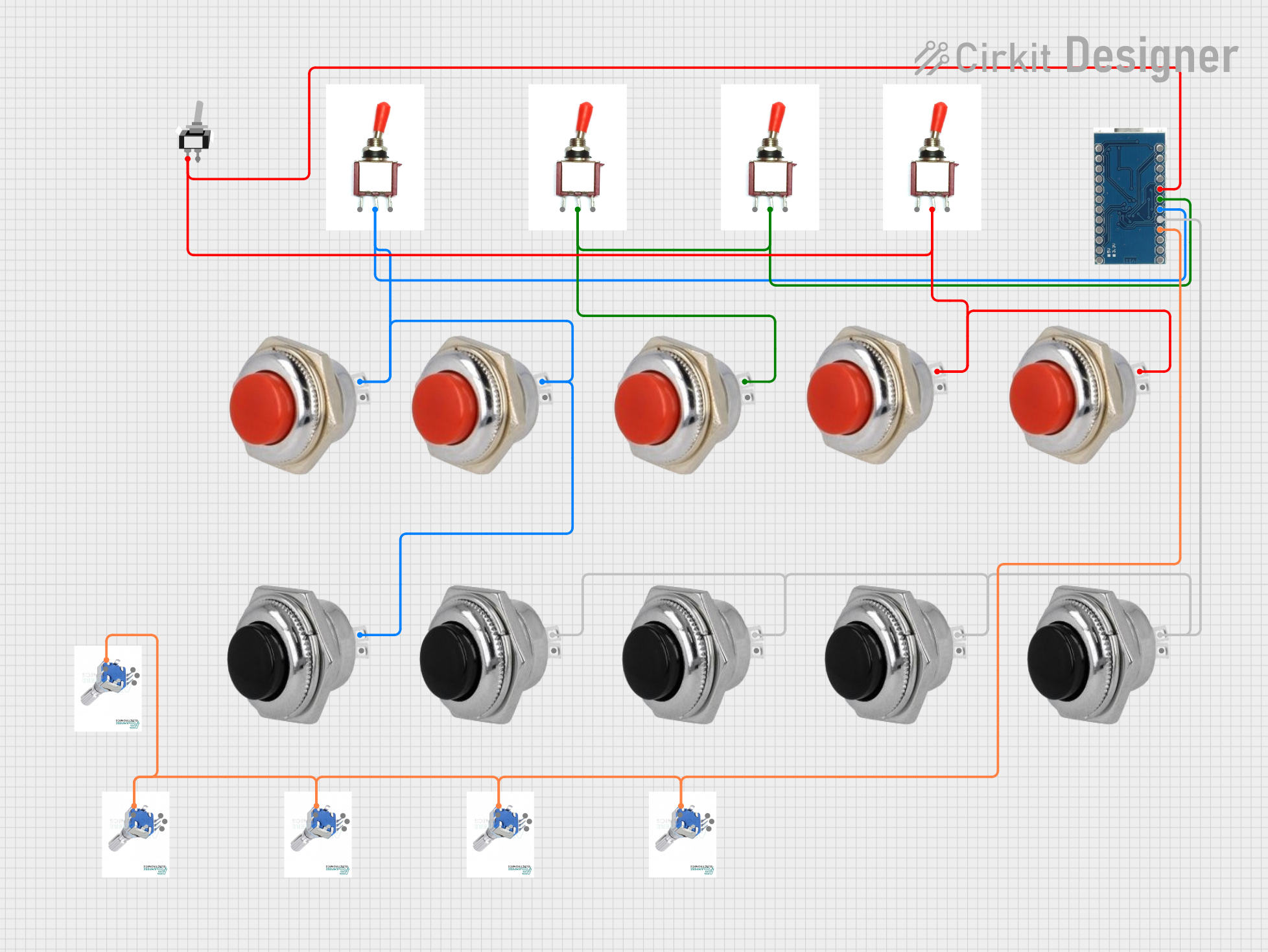 Open Project in Cirkit Designer
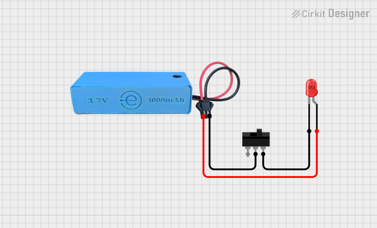 Open Project in Cirkit Designer
Explore Projects Built with Momentary Switch
Open Project in Cirkit DesignerOpen Project in Cirkit DesignerOpen Project in Cirkit DesignerOpen Project in Cirkit DesignerTechnical Specifications
- Type: Normally Open (NO) or Normally Closed (NC)
- Voltage Rating: Typically 3V to 250V (varies by model)
- Current Rating: Typically 0.5A to 5A (varies by model)
- Contact Resistance: < 50 mΩ
- Insulation Resistance: > 100 MΩ
- Mechanical Life: 100,000 to 1,000,000 actuations (varies by model)
- Operating Temperature: -20°C to +70°C (typical)
Pin Configuration and Descriptions
Momentary switches generally have two or more pins. Below is a table describing the pin configuration for a basic two-pin momentary switch:
| Pin | Description |
|---|---|
| Pin 1 | Connects to one side of the circuit |
| Pin 2 | Connects to the other side of the circuit |
For a four-pin momentary switch (commonly used in breadboards), the pins are typically arranged in pairs:
| Pin | Description |
|---|---|
| Pin 1 | Connects to one side of the circuit (internally connected to Pin 2) |
| Pin 2 | Connects to one side of the circuit (internally connected to Pin 1) |
| Pin 3 | Connects to the other side of the circuit (internally connected to Pin 4) |
| Pin 4 | Connects to the other side of the circuit (internally connected to Pin 3) |
Usage Instructions
How to Use the Component in a Circuit
- Identify the Pins: For a two-pin switch, simply connect one pin to the power source and the other to the load or input. For a four-pin switch, identify the pairs of internally connected pins (use a multimeter if necessary).
- Connect to the Circuit:
- For a Normally Open (NO) switch, the circuit will only close (allow current to flow) when the switch is pressed.
- For a Normally Closed (NC) switch, the circuit will remain closed until the switch is pressed.
- Debounce the Switch: Momentary switches can produce electrical noise or "bouncing" when pressed. Use a capacitor or software debounce logic to ensure stable operation.
- Test the Circuit: Verify the switch operation by pressing and releasing it while monitoring the circuit behavior.
Important Considerations and Best Practices
- Voltage and Current Ratings: Ensure the switch can handle the voltage and current of your circuit to avoid damage.
- Debouncing: Use a 10nF to 100nF capacitor across the switch terminals or implement software debouncing in microcontroller-based circuits.
- Mounting: Secure the switch properly to prevent mechanical stress or accidental disconnection.
- Polarity: Momentary switches are non-polarized, so pin orientation does not matter.
Example: Connecting a Momentary Switch to an Arduino UNO
Below is an example of how to connect a momentary switch to an Arduino UNO and read its state:
Circuit Setup
- Connect one pin of the momentary switch to digital pin 2 on the Arduino.
- Connect the other pin of the switch to GND.
- Use a 10kΩ pull-up resistor between digital pin 2 and 5V to ensure a stable HIGH state when the switch is not pressed.
Arduino Code
// Define the pin connected to the momentary switch
const int switchPin = 2;

// Variable to store the switch state
int switchState = 0;

void setup() {
  // Set the switch pin as input with pull-up resistor
  pinMode(switchPin, INPUT_PULLUP);

  // Initialize serial communication for debugging
  Serial.begin(9600);
}

void loop() {
  // Read the state of the switch (LOW when pressed, HIGH when released)
  switchState = digitalRead(switchPin);

  // Print the switch state to the Serial Monitor
  if (switchState == LOW) {
    Serial.println("Switch Pressed");
  } else {
    Serial.println("Switch Released");
  }

  // Add a small delay to avoid spamming the Serial Monitor
  delay(100);
}
Troubleshooting and FAQs
Common Issues Users Might Face
Switch Not Responding:
- Cause: Incorrect wiring or loose connections.
- Solution: Double-check the wiring and ensure all connections are secure.
Switch Bouncing:
- Cause: Electrical noise caused by the mechanical contacts of the switch.
- Solution: Add a capacitor across the switch terminals or implement software debouncing.
Switch Fails to Close the Circuit:
- Cause: Exceeding the voltage or current rating of the switch.
- Solution: Verify the ratings of the switch and ensure they match your circuit requirements.
Intermittent Operation:
- Cause: Worn-out contacts or poor-quality switch.
- Solution: Replace the switch with a new one.
FAQs
Can I use a momentary switch for toggling a state (e.g., turning an LED on/off)?
- Yes, but you will need additional circuitry or programming logic (e.g., using a flip-flop circuit or microcontroller code).
What is the difference between Normally Open (NO) and Normally Closed (NC) switches?
- An NO switch remains open (disconnected) until pressed, while an NC switch remains closed (connected) until pressed.
Do I need a pull-up or pull-down resistor with a momentary switch?
- Yes, a pull-up or pull-down resistor is recommended to ensure a stable HIGH or LOW state when the switch is not pressed.
Can I use a momentary switch with high-power devices?
- Only if the switch's voltage and current ratings are sufficient. Otherwise, use the switch to control a relay or transistor for high-power applications.