
How to Use L3G4200D (LGA16-4x4): Examples, Pinouts, and Specs
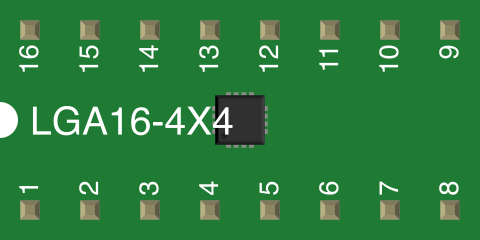
 Design with L3G4200D (LGA16-4x4) in Cirkit Designer
Introduction
The L3G4200D is a 3-axis gyroscope sensor designed to measure angular velocity along the X, Y, and Z axes. It is housed in a compact LGA16 (4x4 mm) package, making it ideal for space-constrained applications. This sensor is widely used in motion sensing, robotics, gaming devices, and image stabilization systems. Its high precision and low power consumption make it a popular choice for embedded systems and IoT devices.
Explore Projects Built with L3G4200D (LGA16-4x4)
 Open Project in Cirkit Designer
 Open Project in Cirkit Designer
 Open Project in Cirkit Designer
 Open Project in Cirkit Designer
Explore Projects Built with L3G4200D (LGA16-4x4)
Open Project in Cirkit DesignerOpen Project in Cirkit DesignerOpen Project in Cirkit DesignerOpen Project in Cirkit DesignerCommon Applications
- Motion sensing in smartphones and tablets
- Robotics for orientation and navigation
- Gaming controllers for motion-based input
- Camera stabilization systems
- Wearable devices for activity tracking
Technical Specifications
Key Specifications
| Parameter | Value |
|---|---|
| Supply Voltage (Vdd) | 2.4V to 3.6V |
| I/O Voltage (Vdd_IO) | 1.8V to Vdd |
| Angular Rate Range | ±250, ±500, ±2000 dps (selectable) |
| Sensitivity | 8.75, 17.5, 70 mdps/digit |
| Output Data Rate (ODR) | 100 Hz to 800 Hz |
| Communication Interface | I²C (up to 400 kHz) / SPI (up to 10 MHz) |
| Operating Temperature | -40°C to +85°C |
| Package Dimensions | 4x4x1 mm (LGA16) |
Pin Configuration
The L3G4200D has 16 pins in an LGA package. Below is the pinout description:
| Pin Number | Pin Name | Description |
|---|---|---|
| 1 | Vdd | Power supply (2.4V to 3.6V) |
| 2 | Vdd_IO | I/O interface voltage (1.8V to Vdd) |
| 3 | GND | Ground |
| 4 | GND | Ground |
| 5 | SCL/SPC | I²C clock / SPI serial port clock |
| 6 | SDA/SDI/SDO | I²C data / SPI data input/output |
| 7 | CS | SPI chip select (active low) |
| 8 | INT1 | Interrupt 1 output |
| 9 | INT2 | Interrupt 2 output |
| 10 | NC | Not connected |
| 11 | NC | Not connected |
| 12 | NC | Not connected |
| 13 | NC | Not connected |
| 14 | NC | Not connected |
| 15 | NC | Not connected |
| 16 | NC | Not connected |
Usage Instructions
Using the L3G4200D in a Circuit
- Power Supply: Connect the Vdd pin to a 3.3V power source and the Vdd_IO pin to the desired I/O voltage (1.8V to 3.3V). Connect the GND pins to the ground of the circuit.
- Communication Interface: Choose between I²C or SPI for communication:
- For I²C, connect the SCL and SDA pins to the corresponding I²C lines on your microcontroller. Use pull-up resistors (typically 4.7kΩ) on both lines.
- For SPI, connect the SPC, SDI/SDO, and CS pins to the SPI lines on your microcontroller.
- Interrupts: If needed, connect the INT1 and INT2 pins to GPIO pins on your microcontroller to handle interrupts.
- Bypass Capacitors: Place a 0.1 µF ceramic capacitor close to the Vdd pin for noise filtering.
Best Practices
- Use decoupling capacitors to stabilize the power supply.
- Keep the traces for the communication lines as short as possible to reduce noise.
- Ensure proper grounding to avoid signal interference.
- Configure the sensor's sensitivity and output data rate based on your application requirements.
Example Code for Arduino UNO (I²C)
Below is an example of how to interface the L3G4200D with an Arduino UNO using the I²C protocol:
#include <Wire.h>

// L3G4200D I2C address
#define L3G4200D_ADDRESS 0x69

// Register addresses
#define CTRL_REG1 0x20
#define OUT_X_L  0x28

void setup() {
  Wire.begin(); // Initialize I2C communication
  Serial.begin(9600); // Initialize serial communication for debugging

  // Configure the L3G4200D
  Wire.beginTransmission(L3G4200D_ADDRESS);
  Wire.write(CTRL_REG1); // Select control register 1
  Wire.write(0x0F); // Enable X, Y, Z axes and set power mode
  Wire.endTransmission();
}

void loop() {
  int16_t x, y, z;

  // Read angular velocity data
  Wire.beginTransmission(L3G4200D_ADDRESS);
  Wire.write(OUT_X_L | 0x80); // Set auto-increment for multi-byte read
  Wire.endTransmission();
  Wire.requestFrom(L3G4200D_ADDRESS, 6); // Request 6 bytes (X, Y, Z)

  if (Wire.available() == 6) {
    x = Wire.read() | (Wire.read() << 8); // Combine low and high bytes
    y = Wire.read() | (Wire.read() << 8);
    z = Wire.read() | (Wire.read() << 8);
  }

  // Print angular velocity values
  Serial.print("X: ");
  Serial.print(x);
  Serial.print(" Y: ");
  Serial.print(y);
  Serial.print(" Z: ");
  Serial.println(z);

  delay(100); // Delay for readability
}
Troubleshooting and FAQs
Common Issues
No Data Output:
- Ensure the sensor is powered correctly (check Vdd and Vdd_IO connections).
- Verify the I²C or SPI connections and ensure the correct pull-up resistors are used for I²C.
- Check that the sensor is properly initialized (e.g., CTRL_REG1 configuration).
Incorrect or Noisy Readings:
- Ensure proper grounding and minimize noise in the circuit.
- Verify that the sensor's sensitivity and data rate are configured correctly for your application.
- Check for mechanical vibrations or external interference affecting the sensor.
Communication Errors:
- Confirm the I²C address (default is 0x69) or SPI settings.
- Ensure the microcontroller's clock speed is compatible with the sensor's communication interface.
FAQs
Q: Can the L3G4200D operate at 5V?
A: No, the maximum supply voltage for the L3G4200D is 3.6V. Exceeding this limit may damage the sensor.
Q: How do I select the angular rate range?
A: The angular rate range can be configured by writing to the CTRL_REG4 register. Refer to the datasheet for specific register settings.
Q: What is the default I²C address of the L3G4200D?
A: The default I²C address is 0x69. If the SDO pin is connected to GND, the address changes to 0x68.
Q: Can I use the L3G4200D with a 1.8V microcontroller?
A: Yes, connect the Vdd_IO pin to 1.8V to ensure compatibility with the microcontroller's I/O voltage levels.