How to Use Break Beam Receiver: Examples, Pinouts, and Specs
Introduction
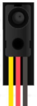
The Break Beam Receiver (Manufacturer Part ID: 2168) by Adafruit Industries is a sensor designed to detect the interruption of a beam of light. It is commonly used in conjunction with a paired infrared (IR) emitter to create a "break beam" system. When an object passes through the beam, the receiver detects the interruption, making it ideal for applications such as object detection, counting, and safety systems.
This component is widely used in automation, robotics, and security systems due to its reliability and ease of integration into electronic circuits.
Explore Projects Built with Break Beam Receiver


Explore Projects Built with Break Beam Receiver
Technical Specifications
The following are the key technical details for the Break Beam Receiver:
General Specifications
- Manufacturer: Adafruit Industries
- Part ID: 2168
- Operating Voltage: 3.3V to 5V DC
- Current Consumption: ~20mA
- Detection Range: Up to 50cm (depending on the paired emitter and environmental conditions)
- Output Type: Digital (Active Low)
- Response Time: <1ms
- Operating Temperature: -25°C to 85°C
- Dimensions: 10mm x 8mm x 5mm (approximate)
Pin Configuration and Descriptions
The Break Beam Receiver has three pins for easy integration into circuits. The pinout is as follows:
| Pin | Name | Description |
|---|---|---|
| 1 | VCC | Power supply input (3.3V to 5V DC). Connect to the positive voltage source. |
| 2 | GND | Ground. Connect to the ground of the circuit. |
| 3 | OUT | Digital output. Outputs LOW when the beam is interrupted, HIGH otherwise. |
Usage Instructions
How to Use the Break Beam Receiver in a Circuit
- Power the Receiver: Connect the VCC pin to a 3.3V or 5V DC power source and the GND pin to the ground of your circuit.
- Connect the Output: Attach the OUT pin to a digital input pin of your microcontroller or to another circuit element (e.g., an LED or buzzer) to monitor the output signal.
- Pair with an IR Emitter: Position the paired IR emitter directly opposite the receiver, ensuring the beam is aligned. The receiver will detect interruptions in the beam caused by objects passing through.
- Monitor the Output: The OUT pin will output a LOW signal when the beam is interrupted and a HIGH signal when the beam is unobstructed.
Important Considerations and Best Practices
- Alignment: Ensure proper alignment between the IR emitter and the receiver for optimal performance.
- Ambient Light: Avoid placing the sensor in areas with excessive ambient IR light (e.g., direct sunlight) to minimize interference.
- Distance: The detection range may vary depending on the strength of the IR emitter and environmental conditions. Test the setup to ensure reliable operation.
- Pull-up Resistor: If the output signal is unstable, consider using a pull-up resistor on the OUT pin to stabilize the signal.
Example: Using the Break Beam Receiver with an Arduino UNO
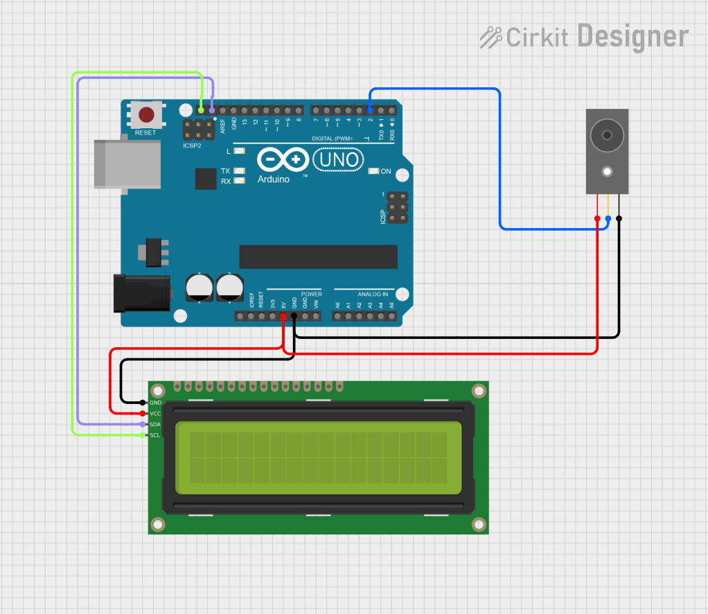
Below is an example of how to connect and use the Break Beam Receiver with an Arduino UNO:
Circuit Connections
- VCC: Connect to the 5V pin on the Arduino.
- GND: Connect to the GND pin on the Arduino.
- OUT: Connect to digital pin 2 on the Arduino.
Arduino Code
// Define the pin connected to the Break Beam Receiver's OUT pin
const int breakBeamPin = 2;

void setup() {
  pinMode(breakBeamPin, INPUT); // Set the pin as an input
  Serial.begin(9600);          // Initialize serial communication
}

void loop() {
  int beamState = digitalRead(breakBeamPin); // Read the state of the beam

  if (beamState == LOW) {
    // Beam is interrupted
    Serial.println("Beam interrupted! Object detected.");
  } else {
    // Beam is not interrupted
    Serial.println("Beam is clear.");
  }

  delay(100); // Small delay to avoid spamming the serial monitor
}
Notes on the Code
- The breakBeamPin is set to digital pin 2, but you can change it to any other digital pin.
- The code continuously monitors the state of the beam and prints the status to the serial monitor.
Troubleshooting and FAQs
Common Issues and Solutions
The receiver does not detect interruptions.
- Solution: Check the alignment between the IR emitter and receiver. Ensure they are directly facing each other.
- Solution: Verify that the IR emitter is powered and functioning correctly.
The output signal is unstable or noisy.
- Solution: Add a pull-up resistor (e.g., 10kΩ) to the OUT pin to stabilize the signal.
- Solution: Ensure the power supply is stable and free from noise.
False triggers in bright environments.
- Solution: Avoid direct sunlight or strong IR sources near the sensor.
- Solution: Use an IR emitter with a higher intensity to improve signal strength.
The detection range is too short.
- Solution: Check the power and alignment of the IR emitter. A stronger emitter may be required for longer distances.
FAQs
Q: Can I use the Break Beam Receiver with a 3.3V microcontroller?
A: Yes, the receiver operates at both 3.3V and 5V, making it compatible with most microcontrollers.Q: What happens if the beam is partially blocked?
A: The receiver may still detect the interruption, depending on the size and position of the obstruction.Q: Can I use multiple Break Beam Receivers in the same project?
A: Yes, you can use multiple receivers, but ensure each has a dedicated IR emitter and proper alignment.Q: Is the receiver waterproof?
A: No, the receiver is not waterproof. Use it in dry environments or enclose it in a protective housing for outdoor use.
By following this documentation, you can effectively integrate the Adafruit Break Beam Receiver (Part ID: 2168) into your projects for reliable object detection and counting applications.