
How to Use SMARTCARD: Examples, Pinouts, and Specs
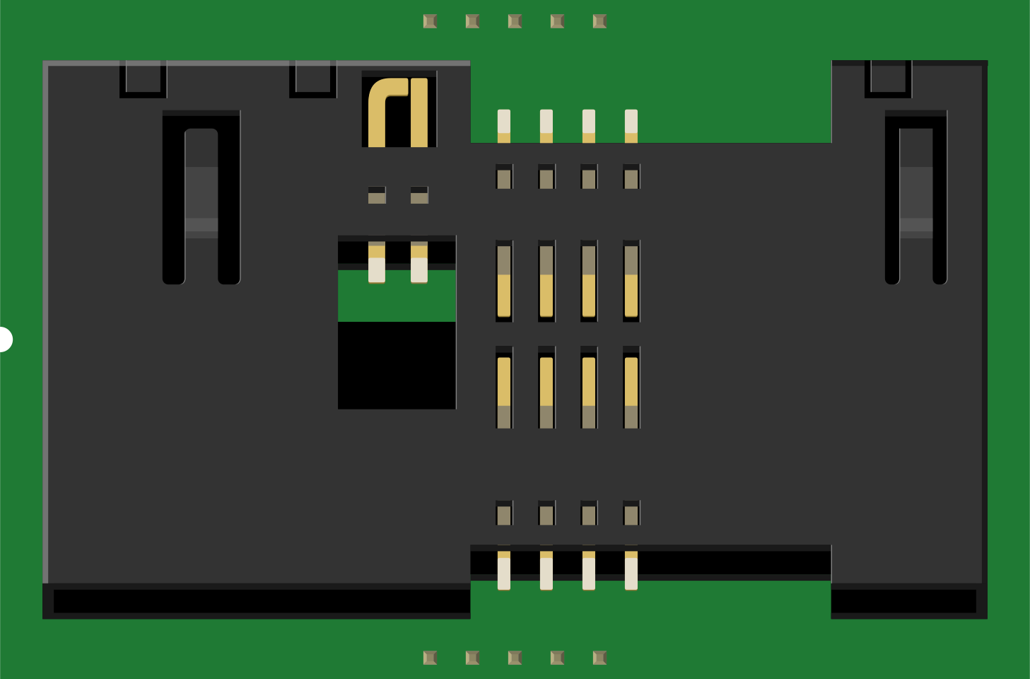
 Design with SMARTCARD in Cirkit Designer
Introduction
A smart card is a portable device that contains an embedded microprocessor or memory chip, enabling secure data storage and processing. It is widely used in applications requiring authentication, secure transactions, and data protection. Common use cases include payment systems (e.g., credit/debit cards), access control systems (e.g., employee ID cards), and secure identification (e.g., government-issued IDs).
Smart cards are valued for their ability to securely store sensitive information, perform cryptographic operations, and interact with external systems via card readers.
Explore Projects Built with SMARTCARD
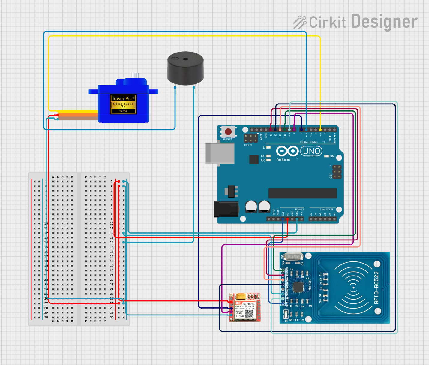 Open Project in Cirkit Designer
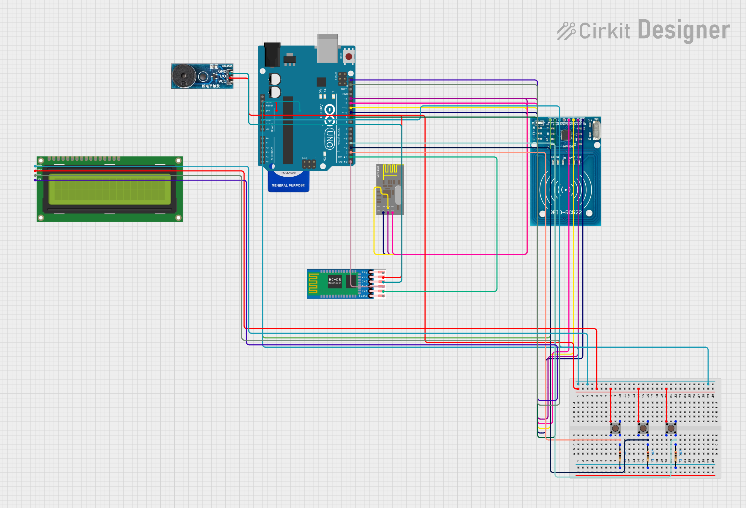 Open Project in Cirkit Designer
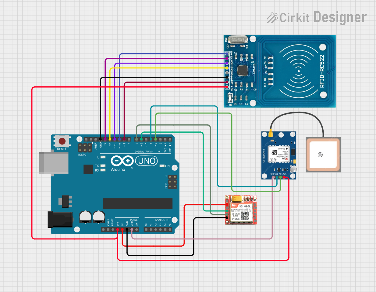 Open Project in Cirkit Designer
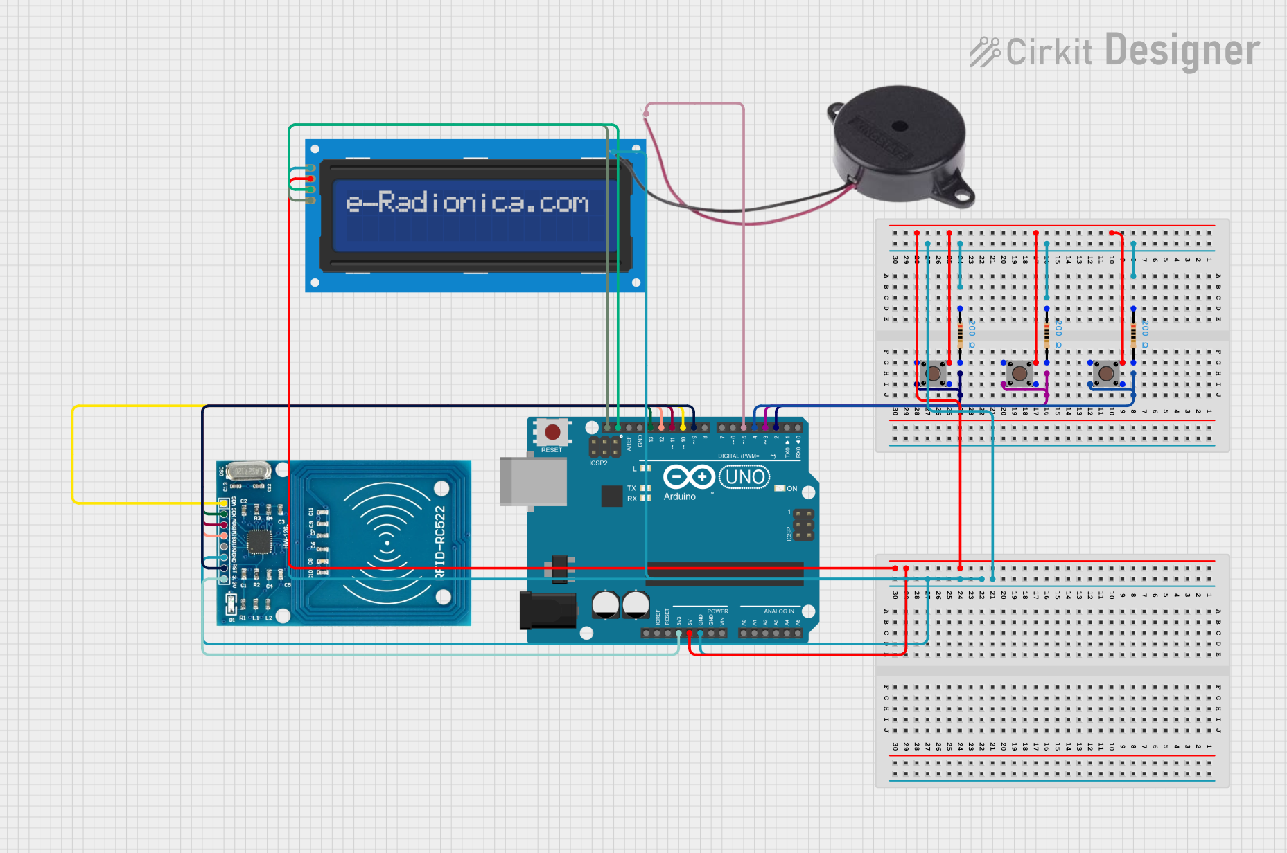 Open Project in Cirkit Designer
Explore Projects Built with SMARTCARD
Open Project in Cirkit DesignerOpen Project in Cirkit DesignerOpen Project in Cirkit DesignerOpen Project in Cirkit DesignerTechnical Specifications
Below are the key technical details of a typical smart card:
- Chip Type: Microprocessor-based or memory-based
- Communication Protocols: ISO/IEC 7816 (contact-based), ISO/IEC 14443 (contactless)
- Operating Voltage: 3V or 5V (depending on the card type)
- Data Storage Capacity: 8 KB to 256 KB (varies by card model)
- Cryptographic Support: RSA, AES, DES, ECC (varies by card type)
- Operating Temperature: -25°C to 85°C
- Durability: Typically rated for 100,000 read/write cycles
Pin Configuration and Descriptions
For contact-based smart cards, the pin configuration follows the ISO/IEC 7816 standard. Below is the pinout description:
| Pin Name | Pin Number | Description |
|---|---|---|
| VCC | 1 | Power supply (3V or 5V) |
| RST | 2 | Reset signal to initialize the card |
| CLK | 3 | Clock signal for synchronization |
| GND | 4 | Ground |
| VPP | 5 | Programming voltage (used in older cards) |
| I/O | 6 | Input/Output for data communication |
| RFU | 7, 8 | Reserved for future use |
For contactless smart cards, communication is typically wireless via an antenna, and no physical pinout is exposed.
Usage Instructions
How to Use the Smart Card in a Circuit
- Connect the Smart Card Reader: Use a compatible smart card reader that supports the ISO/IEC 7816 standard for contact-based cards or an NFC reader for contactless cards.
- Power the Card: Provide the appropriate voltage (3V or 5V) to the VCC pin via the reader.
- Initialize Communication: Send an ATR (Answer to Reset) command to the card via the reader to establish communication.
- Exchange Data: Use the APDU (Application Protocol Data Unit) commands to read/write data or perform cryptographic operations.
- Terminate Communication: Properly close the session to ensure data integrity.
Important Considerations and Best Practices
- Voltage Compatibility: Ensure the card reader provides the correct operating voltage (3V or 5V) to avoid damaging the card.
- Secure Communication: Always use encrypted communication protocols to protect sensitive data.
- Avoid Physical Damage: Handle the card carefully to prevent scratches or damage to the contact pads.
- Firmware Updates: Keep the card reader's firmware up to date for compatibility with newer smart cards.
Example: Using a Smart Card with Arduino UNO
Below is an example of interfacing a smart card reader with an Arduino UNO using the SPI protocol:
#include <SPI.h>
#include <MFRC522.h> // Library for RFID/NFC readers

#define RST_PIN 9    // Reset pin for the reader
#define SS_PIN 10    // Slave Select pin for SPI communication

MFRC522 mfrc522(SS_PIN, RST_PIN); // Create an instance of the reader

void setup() {
  Serial.begin(9600); // Initialize serial communication
  SPI.begin();        // Initialize SPI bus
  mfrc522.PCD_Init(); // Initialize the smart card reader
  Serial.println("Place your smart card near the reader...");
}

void loop() {
  // Check if a card is present
  if (!mfrc522.PICC_IsNewCardPresent() || !mfrc522.PICC_ReadCardSerial()) {
    return; // Exit if no card is detected
  }

  // Print the card's UID (Unique Identifier)
  Serial.print("Card UID: ");
  for (byte i = 0; i < mfrc522.uid.size; i++) {
    Serial.print(mfrc522.uid.uidByte[i], HEX);
    Serial.print(" ");
  }
  Serial.println();

  // Halt the card to stop communication
  mfrc522.PICC_HaltA();
}
Note: This example uses the MFRC522 RFID/NFC module, which supports contactless smart cards. Ensure the library is installed in your Arduino IDE.
Troubleshooting and FAQs
Common Issues
Card Not Detected:
- Ensure the card is properly inserted into the reader (for contact-based cards).
- For contactless cards, ensure the card is within the reader's range.
- Verify the reader's connections to the microcontroller.
Communication Errors:
- Check the wiring between the reader and the microcontroller.
- Ensure the correct communication protocol (e.g., SPI, I2C) is configured in the code.
Incorrect Data Read/Write:
- Verify the APDU commands being sent to the card.
- Ensure the card's memory layout matches the expected format.
FAQs
Q: Can I use a smart card without a reader?
A: No, a smart card requires a compatible reader to interface with external systems.
Q: What is the lifespan of a smart card?
A: Most smart cards are rated for 100,000 read/write cycles and have a lifespan of 5-10 years, depending on usage.
Q: Are smart cards secure?
A: Yes, smart cards are designed with robust security features, including encryption and tamper resistance, to protect sensitive data.
Q: Can I use the same reader for contact and contactless cards?
A: Some advanced readers support both types, but most readers are designed for either contact or contactless cards. Check the reader's specifications.