How to Use Rotary Encoder: Examples, Pinouts, and Specs

Introduction
The KY-040 Rotary Encoder is an electro-mechanical device manufactured by GIAK, designed to convert the angular position or rotation of a shaft into digital signals. Rotary encoders are widely used in various applications such as volume controls, scrolling through menus, and as input devices in user interfaces. The KY-040 is particularly popular among hobbyists and is often used with microcontroller platforms like Arduino due to its simplicity and ease of use.
Explore Projects Built with Rotary Encoder
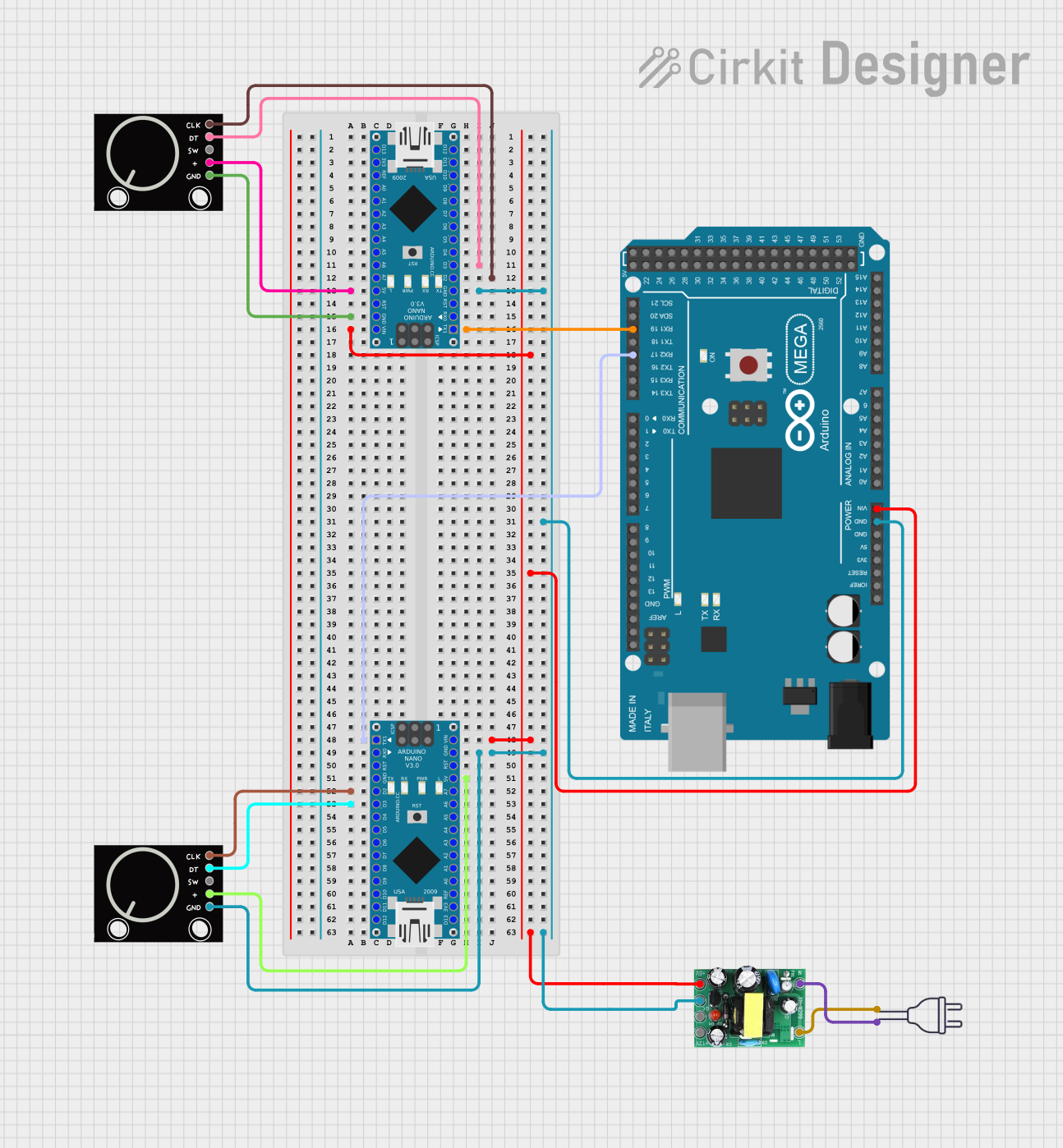
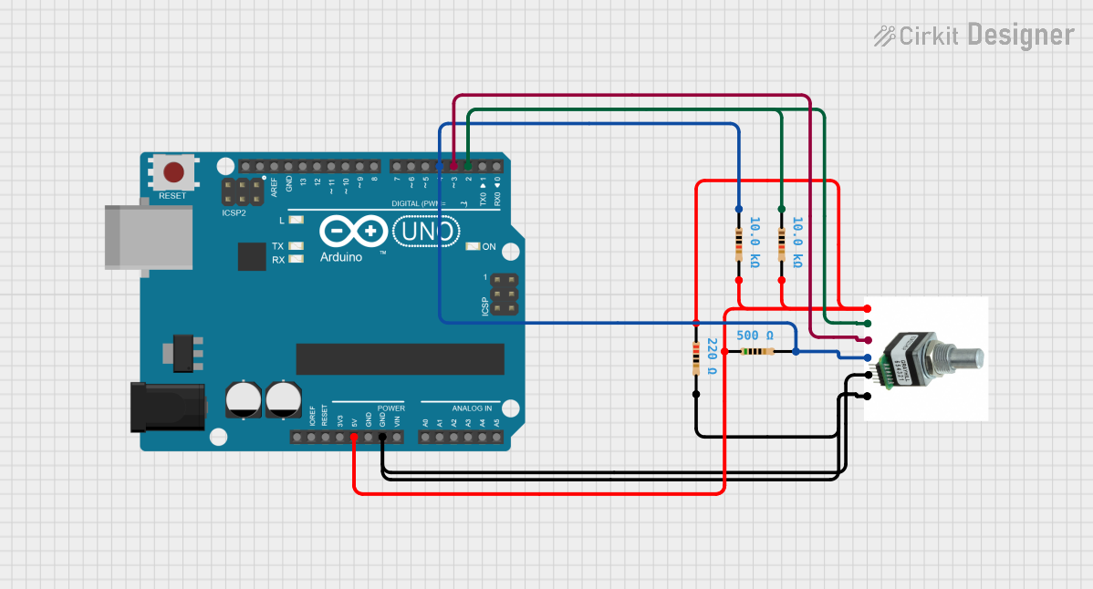
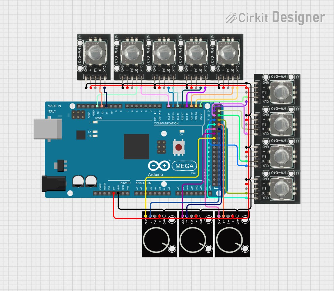
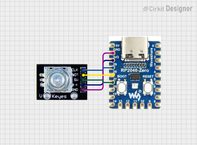
Explore Projects Built with Rotary Encoder
Technical Specifications
Key Technical Details
- Operating Voltage: 5V
- Pulse Number for One Revolution: 20
- Detent Positions: 20 per revolution
- Shaft Diameter: 6mm
- Output: 2-bit quadrature code
- Switch Life: 200,000 cycles
- Operating Temperature: -30°C to +70°C
Pin Configuration and Descriptions
| Pin Number | Description |
|---|---|
| 1 | Ground (GND) |
| 2 | +5V (VCC) |
| 3 | Signal A (CLK) |
| 4 | Signal B (DT) |
| 5 | Push Button (SW) |
Usage Instructions
Connecting to a Circuit
To use the KY-040 Rotary Encoder with an Arduino UNO, connect the pins as follows:
- GND to Arduino GND
- +5V to Arduino 5V
- Signal A (CLK) to a digital pin (e.g., D2)
- Signal B (DT) to another digital pin (e.g., D3)
- Push Button (SW) to another digital pin (e.g., D4)
Important Considerations and Best Practices
- Use pull-up resistors on the CLK and DT pins to ensure stable readings.
- Debounce the rotary encoder in software to prevent false readings due to mechanical noise.
- Implement an interrupt service routine to handle the rotary encoder's signals without missing pulses.
Example Arduino Code
// Define the connections to the Arduino
const int pinCLK = 2; // Connected to CLK on KY-040
const int pinDT = 3;  // Connected to DT on KY-040
const int pinSW = 4;  // Connected to SW on KY-040

// Variables to hold the current and last encoder position
volatile int encoderPos = 0;
int lastEncoderPos = 0;
boolean buttonPressed = false;

// Interrupt service routine for encoder CLK pin
void isr() {
  if (digitalRead(pinDT) != digitalRead(pinCLK)) {
    encoderPos++; // Clockwise
  } else {
    encoderPos--; // Counterclockwise
  }
}

// Setup function
void setup() {
  pinMode(pinCLK, INPUT_PULLUP);
  pinMode(pinDT, INPUT_PULLUP);
  pinMode(pinSW, INPUT_PULLUP);
  attachInterrupt(digitalPinToInterrupt(pinCLK), isr, CHANGE);
  Serial.begin(9600);
}

// Main loop
void loop() {
  if (encoderPos != lastEncoderPos) {
    Serial.println(encoderPos);
    lastEncoderPos = encoderPos;
  }
  if (digitalRead(pinSW) == LOW && !buttonPressed) {
    Serial.println("Button Pressed");
    buttonPressed = true;
  } else if (digitalRead(pinSW) == HIGH && buttonPressed) {
    buttonPressed = false;
  }
}
Troubleshooting and FAQs
Common Issues
- Jittery or Inconsistent Readings: This can be caused by mechanical noise or a lack of debouncing in the code. Implement software debouncing to mitigate this issue.
- No Response from the Encoder: Ensure that the encoder is properly powered and that all connections are secure. Check for any damage to the encoder or its pins.
- Button Not Working: Verify that the button pin is correctly connected and that the internal pull-up resistor is enabled in the code.
Solutions and Tips for Troubleshooting
- Debouncing: Implement a simple debounce algorithm in the interrupt service routine or use a library that handles encoder debouncing.
- Check Connections: Use a multimeter to ensure that there is continuity between the encoder pins and the Arduino pins.
- Serial Output: Use
Serial.println()statements to debug and monitor the encoder's output in real-time.
FAQs
Q: Can I use the KY-040 Rotary Encoder with a 3.3V system? A: Yes, but the output signal levels will be lower, which may require level shifting for some 5V systems.
Q: How can I increase the resolution of the encoder? A: The KY-040 has a fixed resolution of 20 pulses per revolution. To increase the effective resolution, you can use gear ratios or employ software algorithms to interpolate between pulses.
Q: Is it possible to use the encoder without an interrupt? A: Yes, but using interrupts is recommended to ensure all pulses are captured, especially at higher rotation speeds.